CIVIL WORKS GUIDELINES FOR MICRO-HYDROPOWER IN NEPAL
95
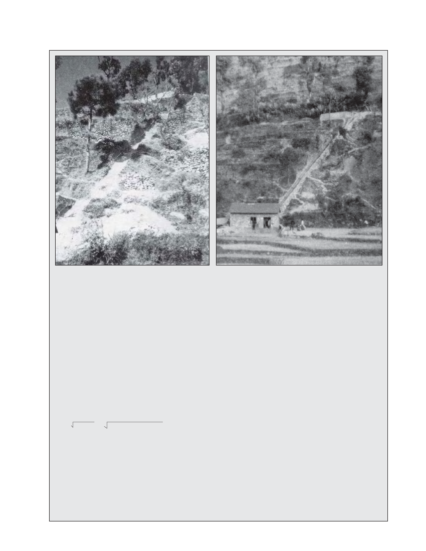
Photo 6.7 Excavation for penstock alignment, Galkot
Photo 6.8 Penstock alignment, Galkot
Example 6.2 Sizing of Jhankre Penstock
The required data for the design of the Jhankre penstock are as follows:
Q = 450 1/s
hgross = 180 m
ten vertical bends, è = 69° , 23°, 26°, 37°, 40°, 2°, 3°, 12°, 8° & 3°, all mitred.
Penstock material: mild steel, flat rolled and site welded, 550 m long. High quality steel plates were bought and tested for tensile
strength at the laboratory. Minimum tensile strength, S = 400 N/mm2 was ensured through the tests.
Turbine type: 3 Pelton turbines with 2 nozzles in each turbine, therefore n = 3 x 2 = 6.
Calculate the required pipe diameter and wall thickness. Note that since the penstock is long, it will be economic to decrease the
thickness at lower heads.
Pipe diameter calculation
Try V = 3.5 m/s.
Calculate the internal pipe diameter:
d = 4Q / ΠV = (4 x 0.450) / (Π x 2.5) = 0.405 m
Calculate wall loss:
From Table 4.3 choose k = 0.06 mm for uncoated mild steel.
k /d = 0.06 / 405 = 0.000148
1.2Q / d = 1.2 (0.450 /0.405) = 1.33
f = 0.0145 (Moody Chart, Figure 4.7)
hwall loss = f ( LV2 / d x 2g) = 0.0145 (550 x 3.52) / 0.405 x 2g
hwall loss = 12.29 m
Inlet loss:
Kentrance = 0.2 for this case (similar to fourth entrance profile in
Table 4.4)
hinlet loss = Kentrance x V2 /2g
hinlet loss = 0.12 m
Exit loss = 0.
= 0.2 x 3.52 / 2g
For mitered bends, interpolate from Table 4.4 :
for θ
for θ
for θ
for θ
for θ
= 69°, Kbend = 0.34
= 23°, Kbend = 0.11
= 26°, Kbend = 0.13
= 37°, Kbend = 0.18
= 40°, Kbend = 0.20