32 CIVIL WORKS GUIDELINES FOR MICRO-HYDROPOWER IN NEPAL
option for a permanent weir in case bedrock is found at the
proposed site. When the weir is on bedrock, deep cut off walls
and riprap are unnecessary. As shown in Figure 3.11, shallow
cut off walls and anchor rods can be used to fix the weir on the
rock surface: the anchor rods should be grouted into the rock.
As mentioned earlier, boulder lined weirs are becoming
popular in small and larger hydro (even up to 60 MW) sector
of Nepal as they are able to better resist the impacts of rolling
boulders during flood events. Furthermore, boulders are also
widely available around river banks. Although heavy earth
moving equipment (e.g., excavators) are used to lay boulders
(sometimes up to 2.5 m size) in larger hydropower projects,
the boulder sizes that could be laid manually (say around
300 mm) could be considered in micro-hydro projects.
High sediment concentration and boulder movement during
flood along with debris flow are common in many small rivers
in the hills and mountains of Nepal. In such conditions,
boulder lined weir appears to be superior to other types. This
type of weir for larger hydro projects mainly consists of central
RCC cut off wall to control seepage and boulder lining on
graded filter (well graded gravel, pebble and small boulders).
At the downstream end of the weir, a random reinforced plum
concrete with 300 mm size boulder armoured surface is also
sometimes incorporated for scour protection. Clay blanket or
impervious membrane could be placed at the upstream end of
the weir if the seepage control cannot be achieved only with
a central cut off wall. The clay blanket needs to be placed
beneath the graded filter on a geotextile wrapper. One
important point to be considered is that the downstream side
slope of the weir should not be steeper than 1 vertical to 6
horizontal to minimise the impact of rolling boulders. However
the upstream side slope could be as high as 1 vertical to 2
horizontal. In this type of weir, sediment deposition at the
upstream side of the weir crest will occur with time. Thus
intake orifice sizing and siting are some of the challenges
here and special attention in designing to ensure flow
availability all times together with minimal sediment entry.
A typical boulder line weir section is shown in Figure 3.11
3.6.5 HEAD OVER WEIR
As stated earlier, placing a weir across the river raises the
water level. Any excess flow that is not withdrawn into the
intake flows over the weir. The discharge over the weir is
given by the following equation:
Q = Cw x Lweir x (hovertop)1.5
Figure 3.11: Boulder lined weir
where:
Q = Discharge over the weir in m3
L weir = Length of weir in m
hovertop = Head over the weir crest level in m
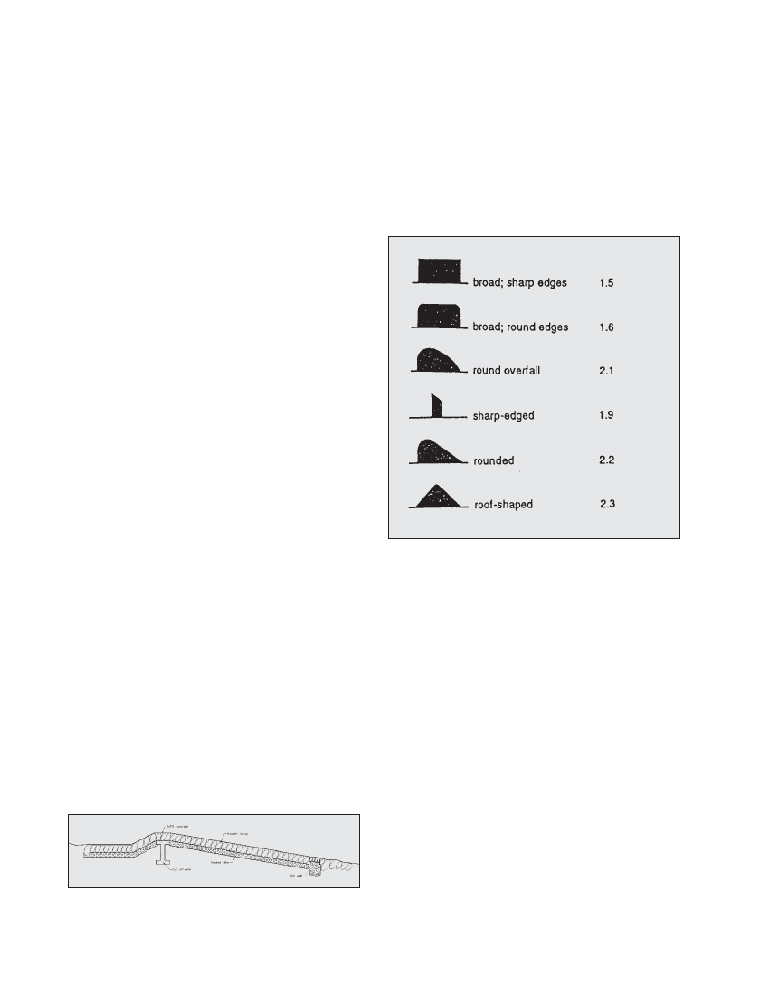
Cw= Weir coefficient which varies according to the weir profile.
Cw for different weir profiles is shown in Table 3.3. In micro-
hydro, the weir is usually broad with round edges and
therefore Cw is l.6 .
Profile of crest of weir C w
Profile of crest of weir
Cw
Table 3.2: Profile of crest of weir
The weir equation is also useful in calculating the flood levels
at the intake if the flood discharge is known or can be
calculated based on the river hydrology. Once the flood levels
are known, the flood protection walls at the riverbank can be
designed. For known discharge over the weir, the head over
the weir (and hence the water level at the intake) can be
calculated by rewriting the weir equation as follows:
hovertop = [Q/(Cw x L weir )]0.667
Calculation of head over a weir can be seen in Example 3.2
3.7 Bottom intakes
3.7.1 DESCRIPTION
The bottom intake, also known as a Tyrolean or trench intake,
is a grille-like opening that captures water from the bed of the
river and drops it directly into the headrace. The flow generally
passes through an opening in a wing wall of the intake
structure and away from the river. In some cases the grille
may cover a small chamber, but generally the bottom intake is
designed as a trench, perpendicular to the direction of the
river flow.