74 CIVIL WORKS GUIDELINES FOR MICRO-HYDROPOWER IN NEPAL
Ystorage = Vsediment / A
Where Ystoraeis the storage depth in the settling basin below
the hydraulic depth (y) discussed earlier, and A is the plan
area. The hydraulic depth and the storage depth are also
shown in Figure 5.3.
5.3.6 COMPONENTS OF A SETTLING BASIN
The settling basin has three distinct zones; the inlet, settling
and outlet zones. These are discussed below and shown in
Figures 5.3 and 5.4.
Inlet zone
This is the initial zone where the transition from the headrace
to the settling basin occurs and there is a gradual expansion
in the basin width.
The design of the inlet is important to the efficiency of the
basin. For high hydraulic efficiency and effective use of the
basin, the inlet should distribute the inflow and suspended
sediment over the full cross sectional area of the settling zone.
Various research data show that horizontal velocity variations
across the width of a rectangular tank affect the hydraulic
efficiency considerably more than velocity variations in depth.
Therefore, attention needs to be given to uniform flow
distribution in the horizontal plane. The following methods
are used in the inlet zone to achieve a good flow distribution:
Photo 5.2 Sliding gate at settling basin entrance, Peru
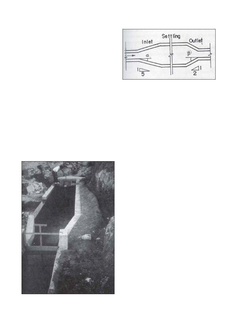
Figure 5.4 Expansion and contraction ration in settling basin
Gradual expansion of the inlet channel. This is the most
commonly used method in micro-hydro schemes.To
determine the length of the inlet zone, set the horizontal
expansion ratio at about 1:5 (a = 11°) as shown in Figure
5.4. This will allow an even flow distribution at the beginning
of the settling zone. The vertical expan-sion ratio can be
higher at about 1:2 (a = 27°) as shown in Figure 5.3.
Another option is to incorporate a weir as can be seen in
the Galkot settling basin (Drawing 420/04/3C01).
Troughs with slots or orifices in walls or bottom.
Baffle walls
Note that orifices or baffle walls are often used in water
treatment facilities where extremely low velocity is required
but these methods are rarely used in micro-hydro schemes.
In some schemes in Peru, a sliding gate is installed in front of
the settling basin as shown in Photograph 5.2. During
flushing, the gate is initially closed, impounding water behind
it. When the settling basin is emptied, the gate is opened and
the sudden rush of the impounded water flushes out any
sediment that has remained inside the basin.
Settling zone
The basin reaches the required width at the beginning of this
zone. Particles are settled, stored and flushed in this zone.
The length of this zone is longer than the inlet or the outlet
zones. It should be noted that long narrow basins perform
better than short wide basins. A range of 4 to 10 is
recommended for the ratio of the length to width (L/B). Basin
shape can also be improved by subdivision with a longitudinal
divide wall, since this doubles the L/B ratio for a given basin
length. Also, the longitudinal divide wall can assist in the
operation of the scheme. For example, the sediment in one
sub-basin can be flushed while the other is in operation,
producing half the power output. Without the subdivision,
the plant would have to be closed during flushing.
Provision for flushing the stored sediment should be at the
end of the settling basin. A floor slope of 1:20 to 1:51 in the
settling zone facilitates flushing.
Outlet zone
This forms the transition from the settling zone to the
headrace. The transition can be more abrupt than the inlet