CIVIL WORKS GUIDELINES FOR MICRO-HYDROPOWER IN NEPAL
87
pipe, support piers and anchor blocks, and in case of pipe
bursts unstable slopes will cause further erosion and
landslides. Slope stability is discussed in detail in Chapter 9.
Other site specific conditions
Apart from the above criteria, there may be other site specific
conditions that dictate the penstock alignment. For example,
if the alignment crosses a local trail, this section should either
be buried or high enough above the ground such that people
and cattle can walk underneath. The Jhankre mini-hydro
penstock alignment is an example where a site specific
Photo 6.5 Penstock alignment high above the ground to
allow access for people and cattle, Jhankre mini-hydro
condition governed the penstock alignment. There is
cultivated land between the intake and powerhouse of this
scheme, so the penstock was aligned mostly along the edge of
the cultivated land. At one section this was not possible and
the alignment had to traverse the cultivated fields. Since it
was not possible to bury the pipes at this section (due to
downstream alignment), a few of the support piers were sized
to be 2 m high as shown in Photograph 6.5. This resulted in
a dear space of about 2.5 m under the penstock, which allows
farmers and cattle to walk underneath.
6.2.2 PROFILE OF THE SELECTED ALIGNMENT
Based on the site survey, a plan and profile of the penstock
alignment should be prepared at the design office as follows:
The ground profile should first be drawn using an
appropriate scale. Same scale should be used for both
horizontal and vertical lengths so that the bend angles are
true angles, which minimises the likelihood of errors. If
the alignment also has horizontal bends, then a plan view
should also be prepared to show horizontal bend angles.
Once the ground profile has been prepared, the penstock
pipe should be drawn on it such that the number of bends
is kept to a minimum. In general for above ground alignment
the support pier height should be minimised unless some
of them need to be increased to avoid small angle bends.
Similarly, excavation should be minimised for the buried
section unless deeper trenches are required at short sections
to avoid small angle bends. Optimising the alignment will
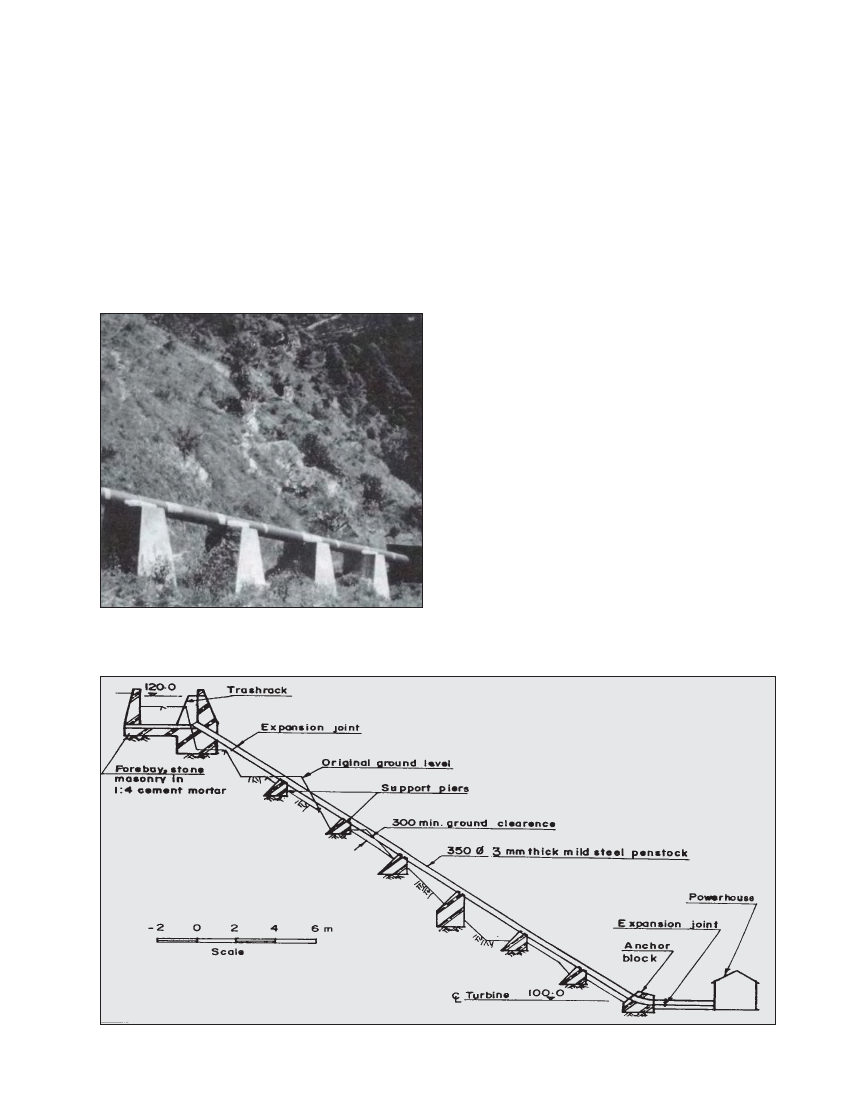
require some iterations. An example of a penstock profile is
shown in Figure 6.1.
For above ground penstock sections, a minimum ground
clearance of 300 mm is recommended to keep the pipe dry
and for ease of maintenance such as painting.
Figure 6.1 Typical penstock profile