52 CIVIL WORKS GUIDELINES FOR MICRO-HYDROPOWER IN NEPAL
Note that when the canal alignment has already been fixed (i.e, fixed canal bed slope, S) as in the case of the Galkot scheme, there
is little control in the velocity. The velocity can be slightly modified by changing the cross sectional area but it will be difficult to make
significant changes. For example, the velocity in the 1/92 slope canal section of the Galkot scheme is about 2 m/s. However, this
was found to be more economical (i.e., reshaping the existing canal) than realigning the canal alignment to reduce the slope. This
implies that the steeper sections of the canal may require more maintenance work than the gentler sections. This is one reason for
plastering the inside surfaces of the canal.
Also, note that earth irrigation canals are generally steeper since ‘n’ (roughness coefficient) is higher. When such canals are
modified as headrace, they become smoother (use of cement mortar, plaster, better shape, etc.) and hence can have higher
velocities.
3.4 Spillways
3.4.1 LOCATION OF SPILLWAYS
As mentioned earlier, spillways are required in headrace canals
to spill excess flows during the monsoon and in case of obstruc-
tion in the canals. Similarly, spillways are also required at the
forebay to spill the entire design flow in case of sudden valve
closure at the powerhouse .
The excess flows that are discharged via a spillway should be
safely diverted into the stream or nearby gully such that they
do not cause any erosion or damage to other structures.
Sometimes, this may require the construction of a channel to
the natural water course. Locating spillways close to a gully
will save the cost of channel construction as can be seen in
Photographs 4.11 and 4.12. .
4.4.2 SPILLWAY DESIGN
Where water is ponding at a downstream regulator such as in
a forebay, the design of spillways can be based on the weir
equation discussed in Chapter 3.
Q = C L (h )spillway
1.5
w spillway overtop
where:
Qspillway
Lspillway
hovertop
= discharge over the spillway in m3/s
= length of the spillway in m
= head over the spillway in m (i.e. height of
water over the spillway)
Cw = a coefficient (similar to weir coefficient)
which varies according to the spillway profile. Cw for different
weir profiles is shown in Table 3.3 (Chapter 3).
The design steps are as follows:
Calculate the flow through the intake during floods as
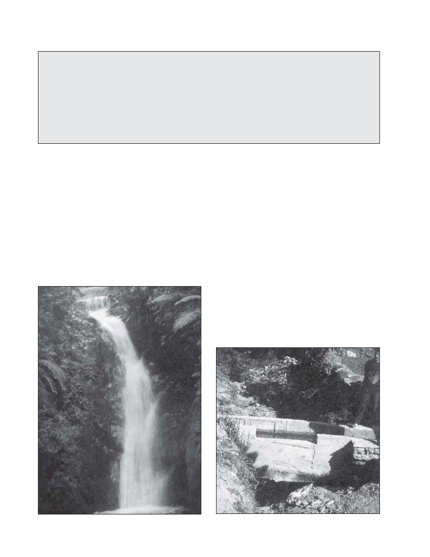
Photo 4.11 Overflow from the forebay over a rock cliff, Dhading micro-
hydro Nepal.
Photo 4.12 Spillway on a crossing where the excess flow is
discharged into a gully, Galkot micro-hydro scheme, Baglung, Nepal.