36 CIVIL WORKS GUIDELINES FOR MICRO-HYDROPOWER IN NEPAL
Example 3.3 Sizing of a bottom intake
A suitable site has been located for a bottom intake. The river width at this area is 5 m and the depth is 0.5 m (i.e. ho = 0.5 m).
A velocity of 3 m/s was measured at the intake site. The design flow (QA) required for power generation is 0.40 m3/s. Select
an appropriate size for the bottom intake.
Design calculations
Choose 20 mm diameter round bars for the trashrack.
µ = 0.85 for round bars (from Figure 3.12) Set the clear
spacing between the bars,
Or h = 2/3 x 0.927 x 0.96 = 0.59 m
c = 0.6 a/b cos3/2ß
c = 0.6 x (0.012 / 0.032) x cos3/2 (ß 8°) = 0.22
a = 12mm
Now use the bottom intake equation:
Centre to centre distance between bars,
d= 32mm
Set the inclination of the trashrack ß = 8° (The inclination of
the trashrack should be equal to or slightly greater than the
river gradient)
For ß = 8° , X = 0.927
QA= 2/3 cµbL 2gh
QA= 2/3 x 0.22 x 0.85x b x L 2x9.8xO.59
QA = 0.42 x b x L
With QA = 0.40 m3/s:
b x L = 0.40 / 0.42 = 0.95 m2
h = 2/3 X . hE
hE = 0.5 + 32/2g = 0.96 m
or L = 0.95 / b
Select the width of the trashrack, b = 2 m L = 0.95/2 = 0.48 m.
Increase the length by 20%: L= 0.48 x 1.2 = 0.57 m. The
proposed dimensions of the bottom intake are as follows:
Width of the opening, b = 2.0 m (at right angles to the flow)
Length of the opening, L = 0.6 m (parallel to the river flow)
Trashrack bar size = 20 mm diameter round bars
Bar spacing = 32 mm centre to centre
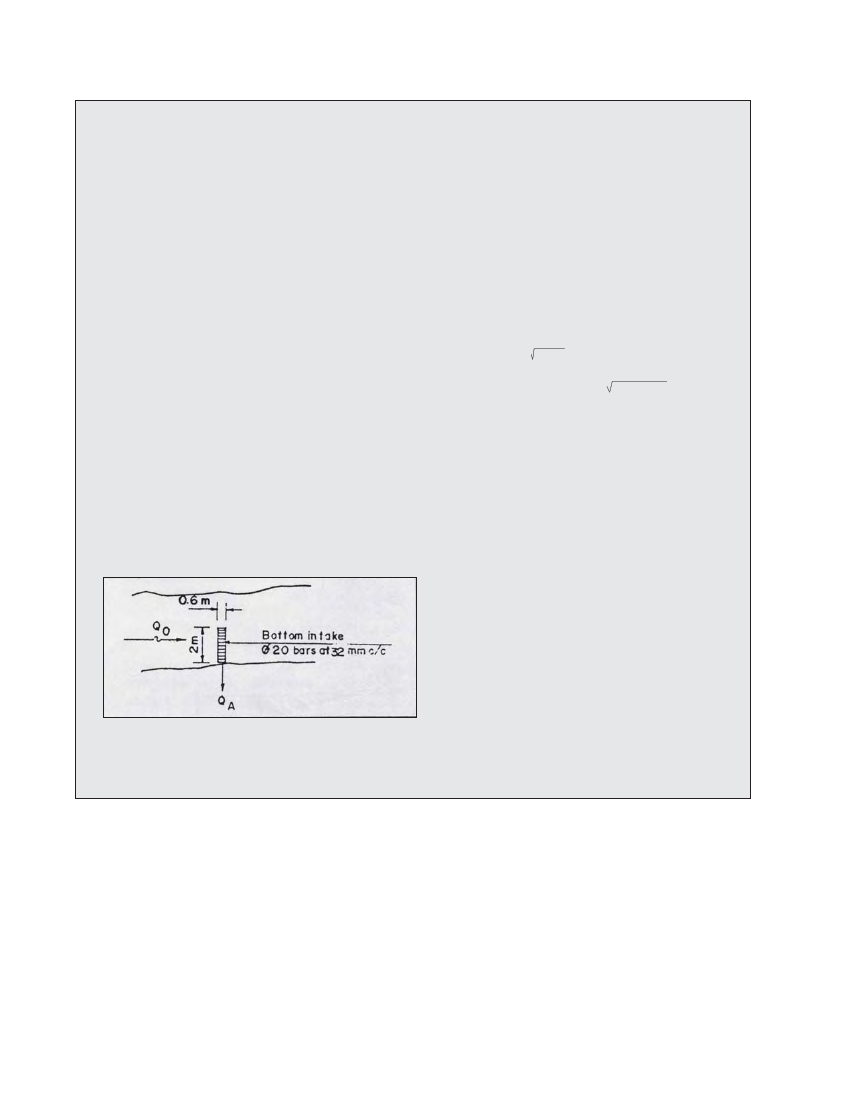
Figure 3.14 Dimension for the bottom of Example 3.3
The plan of this proposed bottom intake is shown in Figure 3.14.
river (vo2/2g). For steep rivers, the flow velocity should be
measured since the velocity head can be high.
X = a function of the inclination of the trashrack (P) as
shown in Table 3.4.
C = Correction factor for submerged overfall,
= 0.6 x 4- a/d cos3/2ß
a = clear spacing of the trashrack bars in m.
d = centre to centre distance between the trashrack bars in m,
ß = angle of inclination of the trashrack with respect to the
horizontal in degrees.
µ = contraction coefficient for the trashrack, which
depends on the shape of the bars as shown in Figure 3.12.
Also in the figure, Qo is the river flow upstream of the
intake and Qu is the excess flow in the river downstream of
the intake.
Note that to solve the bottom intake equation, either the length or
the width of the intake opening needs to be set and the other
dimension can then be calculated. The selection of one of these
dimensions depends on the site conditions. For example, if the
length of the trashrack is too small, the headrace canal will require
deeper excavation in the riverbed, which may be difficult. Generally,
the length of the bottom intake should be equal to the width of the
headrace canal, and the width should match the river channel.