64 CIVIL WORKS GUIDELINES FOR MICRO-HYDROPOWER IN NEPAL
Example 4.3 Siklis headworks
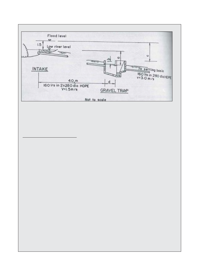
Figure 4.11 Headworks of the 100kw Siklis micro-hydro scheme (Siklis, Nepal)
A sketch of the headworks of the existing 100 kW Siklis micro-hydropower scheme is shown above in Figure 4.11.
Calculate the following:
1. Headloss in intake pipes
2. Design water level in gravel trap
3. Flood flow through intake pipes
4. Spillway length at gravel trap
1. Headloss in intake pipes at design flow
a) Pipe friction
For 280 mm diameter. Class II HDPE pipe manufactured in Nepal, internal diameter = 262 mm
Flow per pipe (Q) = 160/2 = 80 1/s
From Table 4.3, assume k = 0.06 mm
or, k / d = 0.06mm / 262mm = 0.00023
or, 1.2Q / d = 1.2x0.08 / 0.262 =0.366
f = 0.0166 (from Moody Chart, Figure 4.10)
... hwall loss = fLQ2 / i2d5
= 0.0166x40x.0.082 / 12x0.2625 = 0.29m
b) Inlet headloss
Kentrance = 0.8 for this case (Table 4.4}
hinlet loss = Kentrance x V2 / 2g
Check velocity;
V = 4Q / IId2 = 4x0.08 / IIx0.2622 = 1.5 m/s
hinlet loss = 0.8x1.52 / 2x9.8 = 0.09m
c) Exit headless
hexit toss = Kexit x V2/2g
1.0x1.52 / 2x9.8 = 0.11m Total headloss in intake pipes = 0.29 m + 0.09 m + 0.11 m = 0.49 m