116 CIVIL WORKS GUIDELINES FOR MICRO-HYDROPOWER IN NEPAL
Weight of block,
WB = 16.12 x 22 = 354.64 kN
Weight of pipe,
Wp = Π(d + t) t γsteel
= Π x 0.454 x 0.004 x 77
= 0.44 kN/m
Ww = Π(0.4502 ) x 9.8
4
= 1.56 kN/m
Wp + Ww = 2.00 kN / m
Calculate the relevant forces:
1. F1u
= (Wp + Ww) L1u COS α
= (2.00) x2xcos 13° = 3.90 kN
2. F1d
= (Wp + Ww) L1d COS β
= (2.00) x 2 x cos 25° = 3.63 kN
3. Frictional force per support pier:
= ± f (Wp + Ww) L2u COS α
f = 0.25 for steel on steel with tar paper in
between,
= ± 0.25(2.00) x 4 cos 13°
= ± 1.95 kN per support pier
Since there are 8 support piers
F2u on Anchor block = ± 1.95 x 8 = ± 15.6 kN
Note that F2d is zero since an expansion joint is located immedi-
ately downstream of the anchor block.
4. F3
= 15.4 htotal d2sin[(β - α) /2]
= 15.4 x 10⁸ x ( 0.450)2 sin( 25o - 13o)
= 35.20 kN
2
5. F4u
= WpL4u sinα
= 0.44 x 30 x sin13o
= 2.97 kN
Note that F4u is insignificant since α is less than 20° and could have
been ignored as discussed in Table 7.2. F4u has been calculated
here only to show how it is done. F4d is negligible since an expan-
sion joint is placed immediately downstream of the anchor block.,
i.e., L4d ≈ 0 and therefore
6. F6
=100xd = 100x0.450 = 45 kN
7. F7 = 31htotal (d + t)t
F7u = 31 x (108 - 30 sinα) x 0.454 x 0.004
= 5.70 kN
F7d = 31 x 108 x 0.454 x 0.004 = 6.08 kN
Note that as discussed earlier the resultant of these forces is
insignificant.
8 F8 = 2.5 (Q2/d2) sin[(β-α)/2]
= 2.5(0.4502/0.4502) sin[(25°-13°)/2]
= 0.26kN
Note that as discussed earlier, this force is insignificant.
9. F9 = 0 since the pipe diameter does not change.
10. Soil force, F10
From Table 7.3, (γsoil = 20 kN/m3 and Ø = 30° for stiff clay.
Recall that i = 13°
Ka
= cosi- cos2i-cos2Ø = 0.371
cosi+ cos2i-cos2Ø
F10
= γsoilh12
2
cosi x k0 x w
= 20 x 1.82 cos13° x 0.371 x 2
2
= 23.45 kN
This force acts at 1/3 of the buried depth at upstream face of
anchor block from point 0 as shown in Figure 7.7, which is (1/3 x
1.8) = 0.6 m.
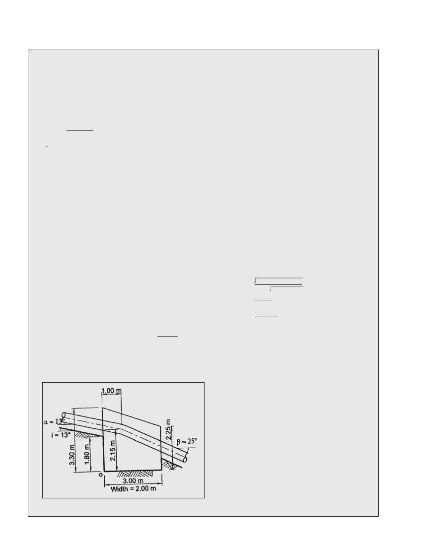
Figure 7.6 Proposed anchor block shape