CIVIL WORKS GUIDELINES FOR MICRO-HYDROPOWER IN NEPAL
115
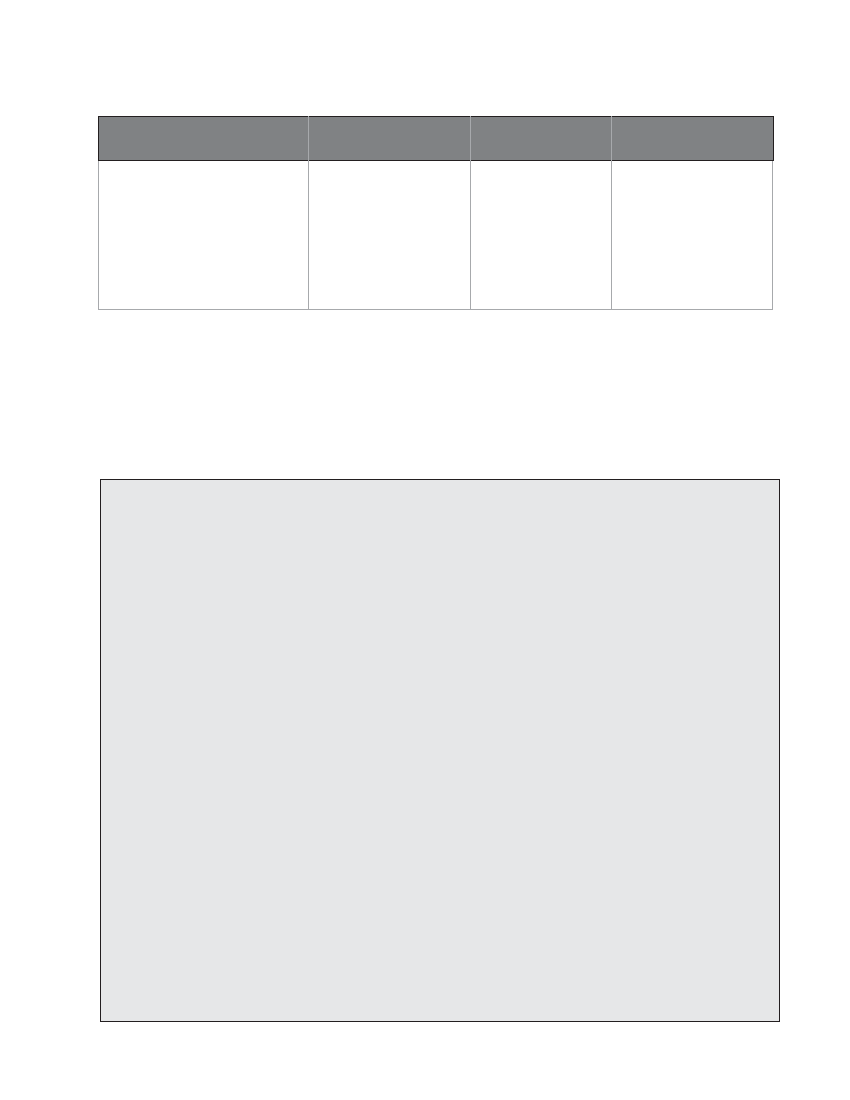
TABLE 7.3 Unit weight ( γ ), angle of friction (Ø) and allowable bearing pressure for different soil types
SOIL TYPE
UNIT WEIGHT, Y (KN/m3)
FRICTION ANGLE (Ø°)
ALLOWABLE BEARING
PRESSURE (KN/m2)
Soft clays and silts
16 22
50
Firm clays and firm sandy clays
17
25
100
Stiff clays and stiff sandy clays
20
30
200
Very stiff boulder clays
20 32
350
Loose well graded sands and
18
31
100
sand /gravel mixture
Safety against sliding
The structure should not slide over its foundation. The
following equation is used to check this condition:
µ ΣV / Σ H ≥ 1.5;
where:
Σ H= sum of horizontal forces
µ = Friction coefficient between the block and the
foundation.
A value of µ = tan Ø, but not exceeding 0.5, is recommended
for friction between masonry or concrete on
soil.
ΣV = the Sum of vertical forces acting on the block
Lbase = length of the base.
Abase = the base area of the block.
Example 7.1 Design of an anchor block
Design for one of the jhankre mini-hydro anchor blocks. The following information is provided:
Pipe diameter = 450 mm,
Pipe thickness = 4 mm.
hgross = 60 m,
hsurge = 48 m,
α = i = 13°, β = 25°
Distance to upstream support pier = 4 m
... L1u = 2m
Distance to downstream support pier = 4 m
... L1d = 2m
Distance to upstream expansion joint = 30 m.
... L4u =30m
There are 8 support piers at 4 m centre to centre spacing (L2u = 4 m) up to the upstream anchor block. To reduce friction, all support
piers are provided with steel shaddle plates and tar paper on top of the plates as in Figure 7.4. An expansion joint will be located just
downstream of the block. The soil type is stiff clay.
CALCULATIONS
Htotal =
=
=
hgross + hsurge
60m + 48m
108
Consider the block shape shown in Figure 7.6.
Block volume excluding volume of the pipe
= {(2.25x3) +(1/2 x 3x 1.05)}x2 - 1xΠx0.4582
/4 cos 13° - 2 x Π x 0.4582 / 4 cos 25° = 16.12 m3
Unit weight of concrete, (γconcrete) = 22 kN /m3