CIVIL WORKS GUIDELINES FOR MICRO-HYDROPOWER IN NEPAL
61
4.6.3 DESIGN PROCEDURE
The design procedure (i.e. selection of an appropriate pipe
diameter) for a headrace pipe is as follows:
1. Choose a standard pipe size from Appendix B, such that the
velocity V is less than 3 m/s (to minimise wall abrasion and
to avoid excessive headloss) and greater than 0.6 m/s (to
avoid sediment being deposited in the pipe). In general,
for HDPE pipes a velocity of 2.5 m/s to 3.0 m/s is found to
be economical.
2. Calculate the actual velocity:
V = 4Q / ∏d2
where:
V is velocity in m/s
Q is design flow in m3/s
d is the pipe internal diameter in m.
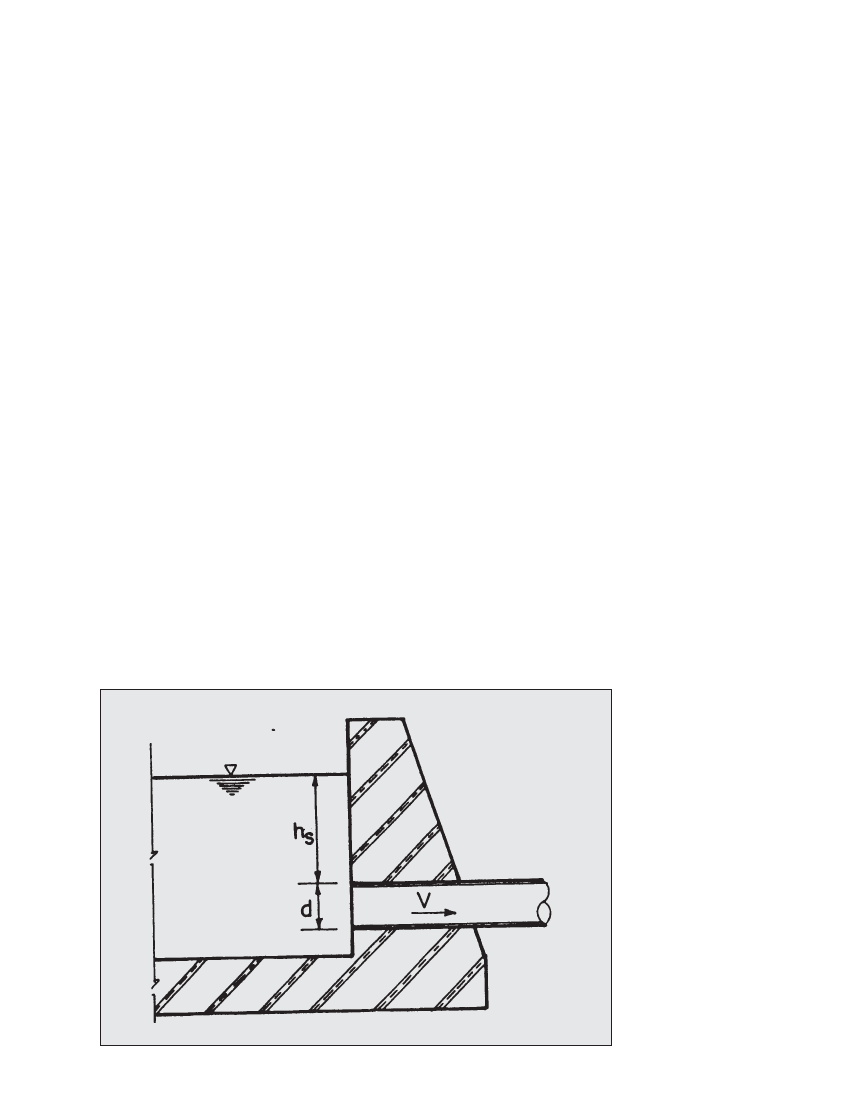
3. At the entrance of the headrace pipe set the submergence
head as follows:
hs >_ 1.5V2 / 2g
where hs is the submergence head in m as shown in Figure
4.9. Note that this is the head from the crown of the pipe. If
the submergence head is less than required, then the pipe
will not be able to convey the design flow (Q) because air
will be drawn into the pipe.
4. Calculate the headloss in the pipe length based on the inlet,
wall friction, bends, valves and exit losses as follows:
Total head loss = wall loss + turbulence losses
The wall losses result from the friction between the
flow and the pipe wall. Wall losses are calculated as
follows:
First determine the roughness value, k in mm from Table
4.3. Note that the values of k in this table are based on
normal age (5-15 years) or condition.
Then use the Moody Chart in Figure 4.10 to find the
corresponding friction factor f for the selected pipe material,
diameter and the design flow.
The wall loss can now be calculated from the following equation:
hwall loss = f (LV2 / dx2g)
In terms of the flow, diameter and length, this equation can
also be rewritten as:
hwall loss =fLQ2 / 12d5
Turbulence losses are calculated as follows:
hturb loss
=V2 / 2g (Kentrance
+
Kbend
+
K +K )contraction
valve
where head loss coefficients, K, are as shown in Table 4.4.
Note that HDPE pipes can be bent (by hand) without causing
any damage if the bend radius is at least 50 times the pipe
diameter. This should be done wherever possible, because:
a) it avoids the need for mitred bends;
b) it avoids the need for anchor blocks to restrain bend
forces (discussed in Chapter 7); and
c) at such large radius, Kbend becomes negligible.
Where a long radius bend is not possible, a sharper bend is required,
and the value of Kbend should be taken from Table 4.4. Mitred
bends will normally be used for steel and HDPE pipelines: these
are fabricated by cutting the pipe at an angle (maximum 15°) and
then welding the ends together to create a bend of up to 30°. For
bends of more than 30°, two or more mitre joints are required.
Figure 4.9 Submergence head for a pipe