106 CIVIL WORKS GUIDELINES FOR MICRO-HYDROPOWER IN NEPAL
The hoop bars should be approximately 150 mm clear of the
pipe, and should extend to 100 mm from the base, so that the
whole weight of the block can be mobilised without cracking.
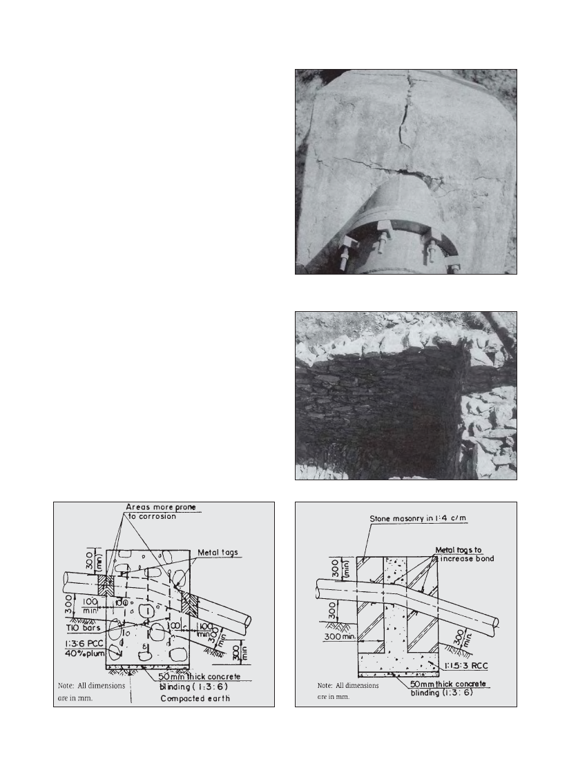
If the reinforcement is inadequate, the block can crack, as
shown in Photograph 7.3. A collar or metal tags may be welded
to the pipe to ensure that the pipe does not slide within the
anchor block. For downward bends, the anchor block is mainly
in compression, therefore a stone masonry structure (1:4
cement mortar) can be considered if costs can be brought
down. Composite anchor blocks can also be considered to save
cost as shown in Figure 7.2. Foundation parts and central
portion of the block can be made of 1:1.5:3 reinforced concrete
and outer portion of the block can be made of stone masonry
in 1:4 (cement: sand) mortar.
The cement requirements for plum concrete and cement
masonry are as follows:
1:3:6 concrete with 40% plums: 132 kg of cement per m3 of
block volume.
1:1.5:3 concrete: 400 kg of cement per m3.
Stone masonry in 1:4 cement mortar: 159 kg of cement per m3.
Although more cement is required for cement masonry blocks,
savings may be made by avoiding the cost of form work (where
wood is expensive) and crushing of stone to prepare
aggregates. Therefore, whether plum concrete or cement
masonry is economical is site specific but this issue should be
investigated if there are a number of downward vertical bends.
Cost can also be reduced by using permanent dry stone walls
as formwork for the buried portion of the anchor block as
shown in Photograph 7.4. At sites where wood is expensive
this approach is worth considering. Both plain concrete or
stone masonry in cement mortar blocks should be cured as
discussed in Chapter 3 by keeping them moist for at least a
week. The design of anchor blocks is covered in Section 7.4.
Photo 7.3 Cracking of the upper surface of an unreinforced anchor
block
Photo 7.4 Use of dry stone wall for forework, Jhankre mini-hydro
Figure 7.1 Anchor Block Section
Figure 7.2 Composite anchor block section