CIVIL WORKS GUIDELINES FOR MICRO-HYDROPOWER IN NEPAL
119
7.4.4 SIZING OF ANCHOR BLOCKS FOR SMALL SCHEMES
For micro-hydro schemes with a gross head less than 60m
and an installed power capacity less than or equal to 20 kW,
the following guidelines can be used to determine the size
of an anchor block:
At a straight section, locate one anchor block after every 30
m distance (as discussed earlier) by placing 1m3 of plum
concrete for each 300mm of pipe diameter. For example, if
the pipe diameter is 200 mm, then:
1 x (200 / 300) =0.67 m3 of concrete volume is
required .
At a penstock bend, where the bend angle is less than 45°
i.e. (β-α), double the concrete volume than what is required
for a straight section. For example if the pipe diameter is
200mm and the bend is 20°, then:
2x(200 / 300) = 1.33m3 of concrete is required for the anchor
block.
Similarly, if the bend angle is larger than 45°, then the
required concrete volume should be three times that for a
straight section. For example if the pipe diameter is 350
mm and the bend is 50°, then:
3x (350/300) = 3.5m3 of concrete is required for the anchor
block.
John Bywater has developed a more sophisticated method of
sizing anchor blocks for small schemes. This is available through
Practical Action.
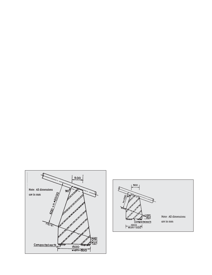
7.4.5 SIZING OF SUPPORT PIERS FOR SMALL SCHEMES
For small schemes (gross head less than 60 m and power
capacity limited to 20 kW) Figures 7.8 and 7.9 can be used as
guidelines to size for support piers.
If the penstock alignment is less than 1 m above the ground,
Figure 7.8 can be used as a guide for the shape of the support
pier. The minimum length and width at the base should be 1
m x 1 m and the top width parallel to the penstock alignment
should be 0.5m. The width at the top perpendicular to the
penstock pipe route should be kept 1 m and the uphill wall
surface should be perpendicular to the penstock pipe. A
minimum foundation depth of 300 mm should be provided.
Similarly, if the penstock pipe is 1-2m above the ground,
Figure 7.9 can be use as a guideline. Note that the structure is
similar to Figure 7.8 except that the base length and width
are 1.5m x 1.5m.
For larger schemes all relevant forces should be resolved and
conditions of stability should be checked as discussed earlier.
7.4.5 Checklist for anchor block and support pier works
Have anchor blocks been located at exposed penstock length
intervals exceeding 30 m even when there are no bends?
For anchor blocks, has a minimum cover of 300 mm around
the pipe been provided? Is adequate reinforcement
included?
If there are a lot of downwards bends and wood is expensive
at site consider using masonry anchor blocks. Also for the
buried sections, dry stone walls can be used as permanent
formwork.
Has adequate foundation depth been provided for both
support piers and anchor blocks? Be sure to include steel
plates and tar paper on support piers to minimise friction.
Have all relevant forces on both support piers and anchor
blocks been checked as discussed in Section 7.4?
Finally refer to Chapter 9 for issues concerning stability.
Figure 7.8 Support pier for small schemes with ground height of less
than 1 m
Figure 7.9 Support pier for small schemes with ground height of 1 m
to 2 m