CIVIL WORKS GUIDELINES FOR MICRO-HYDROPOWER IN NEPAL
81
The trashrack at the forebay should be
placed at 1:3 slope for both efficient
hydraulic performance and ease of
cleaning (such as by raking) as shown in
Figure 5.8. To minimise headless and
blockage, the recommended velocity
through the trashrack is 0.6 m/s. but a
maximum of 1 m/s could be used.
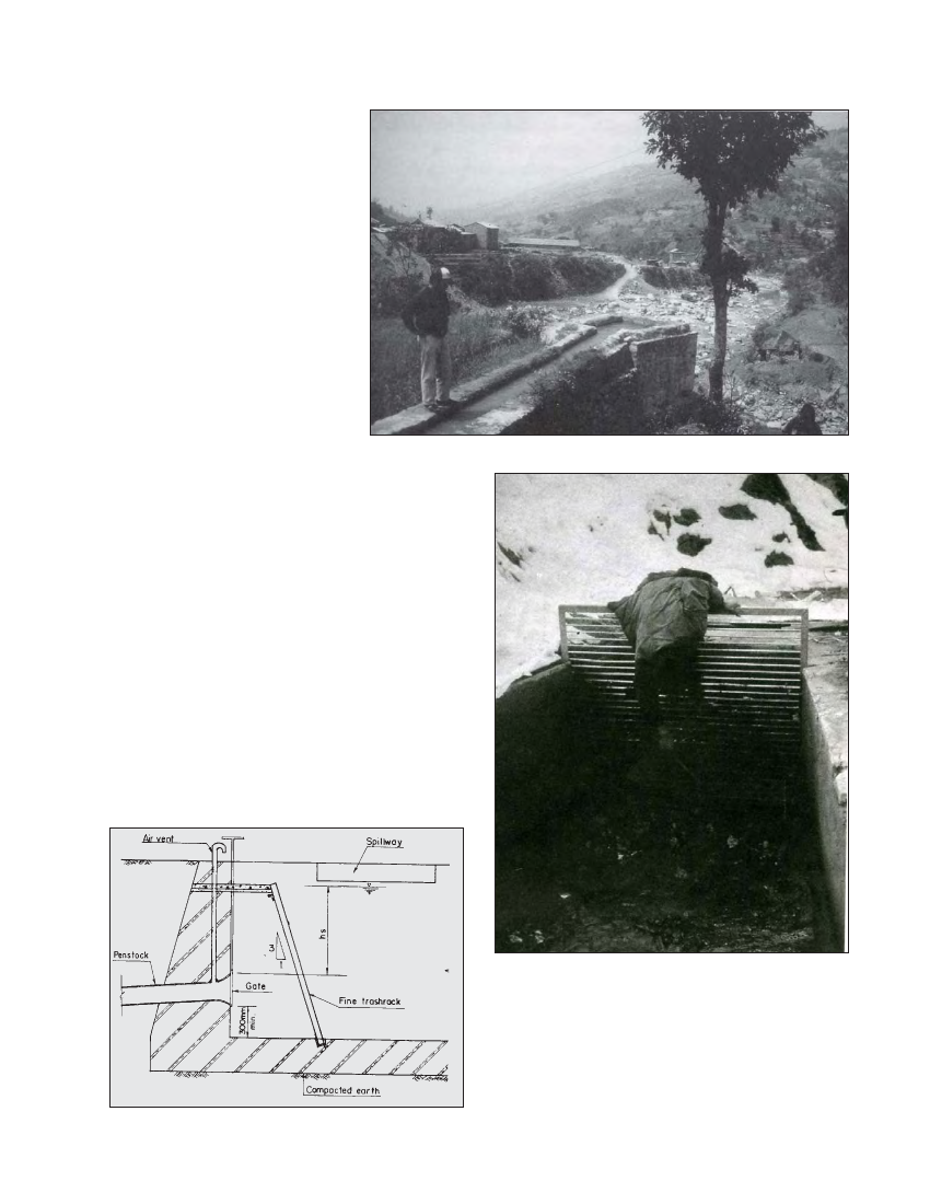
It should also be noted that the trashrack
bars should be placed vertically since
horizontal bars are difficult to clean as
shown in Photograph 5.11. The spacing
between the trashrack bars should be
about half the nozzle diameter for Pelton
turbines and half the runner width for
crossflow turbines. This prevents the
turbines from being obstructed by debris
and minimises the chances of surge.
Photo 5.10 A cement masonry channel and forebay at the top of a steep slope (Dhading)
Cleaning of the trashrack can be minimised by fixing it such that
it is submerged during the design flow as in the case of the
Salleri Chialsa mini-hydro (Photograph 5.12.). Here the top level
of the trashrack is below the design water level. Any floating
debris such as leaves are washed by the flow above the trashrack
and spilled via the spillway. Although this type of arrangement
facilitates self-cleaning of the trashrack, some additional flow
(than the design flow) will be constantly required.
5.4.6 SPILLWAY
As discussed earlier, a spillway should also be incorporated at
the forebay. The spillway should be sized such that it can
release the entire design flow when required. This is because
if the turbine valve is closed during emergencies, the entire
design flow will have to be spilled from the forebay until the
operator reaches the intake or other control structures upstream
of the forebay.
Figure 5.8 Forebay
Figure 5.8 Forebay
Photo 5.11 Cleaning can be difficult with horizontal bars.
Photo 5.11 Cleaning can be difficult with horizontal bars
5.4.7 GATE AND VENT
Incorporating a gate at the entrance of the penstock will make
the maintenance work of the turbine easy. The gate can be
closed, thus emptying the penstock and work can be done in
the turbine. However, a rapid closure of this gate will create a
negative pressure (i.e. vacuum) inside the pipe and could
cause it to collapse. Placing an air intake pipe as shown in
Figure 5.8 will prevent such a situation since air can be drawn