CIVIL WORKS GUIDELINES FOR MICRO-HYDROPOWER IN NEPAL
75
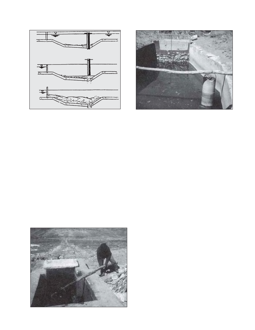
Figure 5.5 Flushing settling basin using the vertical
flush pipe method
expansion (i.e., horizontally 1:2 or p = 26.5° as shown in
Figure 5.4, and vertically 1:1 as shown in Figure 5.3). Note
that if the settling basin is combined with the forebay, then
this zone is not necessary: the forebay structure can be directly
downstream of the settling zone.
The operating water level of the settling basin is generally
controlled at the outlet, sometimes by a weir which may be
designed to operate as submerged in order to conserve head.
5.3.7 FLUSHING ARRANGEMENTS
Vertical Hush pipe method
There are various ways of removing the stored sediment from
the settling basin. An appropriate method for micro-hydro
settling basins is the “vertical flush pipe”. This uses a detach-
able vertical mild steel pipe over a hole in the basin floor. A
drain pipe is fixed below the basin floor to convey the flow
out of the basin. When the vertical flush pipe is lifted, the
water stored in the basin and the incoming flow along with
the sediment are drained through the hole. Apart from being
simple, the other advantage of this system is that it can spill
Photo 5.3 Lifting the flushing mechanism (Jhong)
Photo 5.4 Jharkot settling basin
some excess flow such as during floods when the water level
in the basin is above the normal level. This vertical flush
method is shown schematically in Figure 5.5. The Galkot
settling basin is based on this method as can be seen in
Drawing 420/04/3C01 of Appendix C. Similarly, the jharkot
micro-hydro scheme also uses this method for flushing as can
be seen in Photograph 5.3. The diameter of the flush pipe is
governed by the following criteria:
a) Overflow capacity
It needs to spill the excess flood flow that enters the basin as
shown in Figure 5.6. This is governed by the weir equation,
where the perimeter of the pipe is used for the length as follows:
Qflood =ΠdCwhflood3/2
where:
Qflood is the expected flood flow in the basin
hflood is the depth of water above the vertical pipe during Qflood
This is the height between the top of the vertical flush pipe
and the top of the settling basin wall.
Cw is the weir coefficient for a sharp edged weir, which is 1.9
(see Table 3.3, Chapter 3). The reason for using the sharp
edged weir coefficient is because the pipe thickness is small
compared to the head.
In terms of the pipe diameter, the above equation can be
rewritten as follows:
d = Qflood / 1.9Πhflood 3/2
To ensure draining of excess flow and to prevent spilling of the
design flow the height of the vertical flush pipe should be such
that the top level is 50mm above the design water level. Also
note that if the settling basin is combined with the forebay,
it may be more important to size the flush pipe diameter such that
it is able to spill the design flow. This is because if the turbine
valve is closed during emergencies, the entire design flow will
have to be spilled from the forebay until the operator reaches the
intake or other control structures upstream of the forebay.