46 CIVIL WORKS GUIDELINES FOR MICRO-HYDROPOWER IN NEPAL
4.3 Canal design
4.3.1 DESIGN CRITERIA
The following criteria are used for the design of headrace
canals:
Capacity
The headrace canal should be able to carry the design flow
with adequate freeboard. Freeboard is the difference in
elevation between the canal bank top and the design water
level. During monsoon, the river water level is high and
therefore flows higher than the design flow can enter the
intake. Spillways and escapes are required to discharge the
excess flows. Similarly if falling debris or other obstructions
block the canal, the entire flow needs to be safely discharged
into a nearby gully or stream before it induces further instabil-
ity problems.
Velocity
The velocity should be low enough to ensure that the bed and
the walls of the canal are not eroded. The recommended
maximum velocity for different types of canal is shown in
Table 4.1. If the velocity is too low, aquatic plants and moss
will start to grow on the canal and reduce the cross sectional
area. A minimum velocity of 0.4 m/s should be maintained to
prevent the growth of aquatic plants. Also, the velocity in the
headrace canal up to the settling basin needs to be high enough
to prevent sediment deposition.
Headless and seepage
As mentioned earlier headloss and seepage need to be mini-
mised. Headloss is governed by the canal slope. Seepage can
be controlled by choosing the construction materials (earth,
mud or cement mortar canals etc.) appropriate for the ground
conditions.
Side slopes
Theoretically, the optimum cross sectional shape for a canal is
a semi-circle, since it can convey the maximum flow for a
given cross sectional area. Since it is difficult to construct a
semi-circular canal, in practice, a trapezoidal shape (which is
close to a semi-circle) is used. For masonry canals in cement
mortar or plain concrete canals that are continuous, rectangular
shapes (i.e., vertical walls) are recommended unless the
backfill can be well compacted or excavating the required
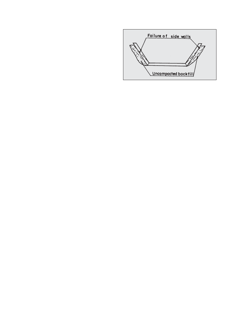
trapezoidal shape is possible. This is because trapezoidal
cement masonry and plain concrete canals’ side walls will
have to depend on the backfill for support. The walls may
crack at the canal bed level (causing seepage) since it may be
difficult to compact the backfill properly behind the walls, as
shown in Figure 4.5. Recommended side slopes for different
canal types are shown in Table 4.2.
Stability
Not only should the canal be on stable ground but the areas
above and below the alignment also need to be stable. When
Figure 4.5 Failure of side walls for rigid trapezoidal canals
determining the canal route at site, the signs of stability and
instability discussed in Chapter 2 should be referred to.
The canal design should address stability issues such as
protection against rockfalls, landslides and storm runoff.
Covering canals by placing concrete slabs (or flat stones) and
some soil cover (to absorb the impact of falling rocks) can be
an appropriate solution if a small length of the canal is
vulnerable to rockfalls. Examples of concrete slabs can be seen
in the superpassage drawings of the Galkot scheme in
Appendix C.
Economics
Similar to any other engineering structure, the design of the
canal should be such that the cost is minimised. This is
especially important in the case of a long headrace canal since
optimising the design will result in substantial saving in the
total project cost. Design optimisation or minimising costs
requires keeping the canal alignment as short as possible
(unless longer lengths are needed to avoid unstable areas
and crossings) as well as minimising excavation and the use
of construction materials, especially cement and stones. For
example, in a micro-hydro scheme, cement masonry canal
could be used only at sections where the soil is porous and/or
seepage is likely to trigger landslides. In the same scheme,
earth and stone masonry in mud mortar canals could be used
at sections where problems associated with seepage are not
expected. Where the headrace canal constitutes a significant
portion of the total project cost, it would be worthwhile to
optimise the canal dimensions.
Optimisation of canal may also be worthwhile if the design
flow is large, the length is long or expensive canal lining is
required. For optimisation of the canal, the least cost method
is generally used. A schematic diagram of the canal
optimisation process is presented in Figure 4.6. Then cost of
1m long canal for a given design flow and different
longitudinal slopes should be calculated. Note that the canal
dimensions (depth and width) are primarily dependent on
the longitudinal slope and hence accounted once the design
flow and the lining type is finalised. Generally the costs
involved are: excavation and lining costs. For simple cost
comparison only lining cost in case of lined canal and
excavation cost in case of unlined canal should is considered