CIVIL WORKS GUIDELINES FOR MICRO-HYDROPOWER IN NEPAL
3
CROSSINGS
These are structures that convey the flow over streams, gullies
or across unstable terrain subject to landslides and erosion.
Aqueducts, super passage, culverts and suspended crossings
are examples of such structures.
PENSTOCK
This is a pipe that conveys water under pressure from the
forebay to the turbine. The penstock pipe usually starts where
the ground profile is steep. Some times a long penstock could
be laid from headwork to the power house if the topography is
suitable (e.g., alignment is suitable for a penstock alignment
right from the intake). In such project layout a forebay is
constructed at the headworks area and is combined with the
settling basin.
ANCHOR BLOCK
An anchor block (thrust block) is an encasement of a penstock
designed to constrain the pipe movement in all direction.
Anchor blocks are placed at all sharp horizontal and vertical
bends, since there are forces at such bends that will tend to
move the pipe out of alignment. Anchor blocks are also required
to resist axial forces in long straight sections of penstock.
SUPPORT PIER
Support piers (also called slide blocks or saddles) are structures
that are used along straight runs of exposed penstock pipe
(between anchor blocks), to prevent the pipe from sagging
and becoming overstressed. They need to resist all vertical
forces such as the weight of the penstock pipe and water.
However, they should allow movement parallel to the penstock
alignment which occurs during thermal expansion and
contraction processes.
POWERHOUSE
This is a building that accommodates and protects the electro-
mechanical equipment such as the turbine, generator and
may include agro-processing units. The electro-mechanical
equipment in the powerhouse converts the potential and
kinetic energy of water into electrical energy.
TAILRACE
This is a channel or a pipe that conveys water from the turbine
(after power generation) back into the stream; generally the
same stream from which water was initially withdrawn.
Detailed descriptions of these components including selection,
design and construction methodology are discussed in
subsequent chapters.
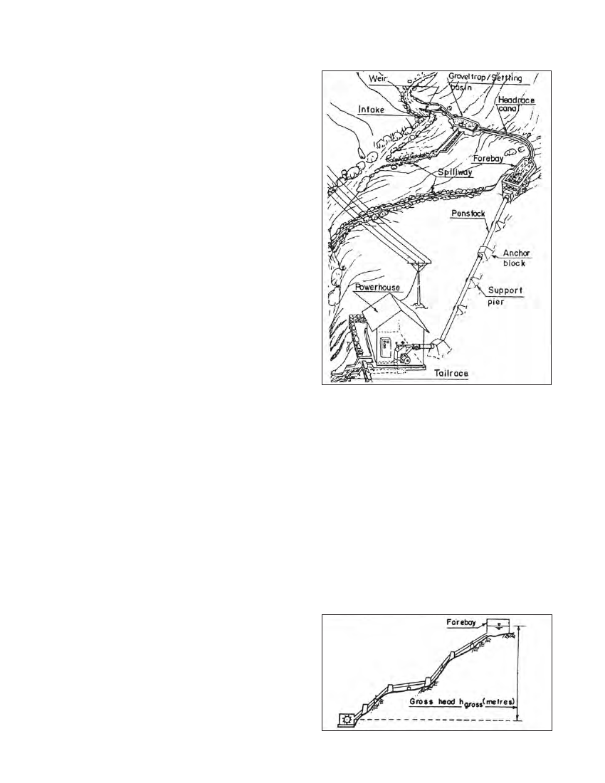
Figure 1.1 Components of a micro-hydro scheme
equation as follows:
P=Q x g x hgross xeo
where:
P is the power produced in kW
Q is the flow in the penstock pipe in m3/s
g is the acceleration due to gravity (9.8 m/s2)
h gross is the gross head available in m
eo is the overall system efficiency
Gross head, h ,gross is the difference between the water level at
the forebay and the turbine centreline level (or tailrace water
surface if a draft tube is used). This is shown schematically in
Figure 1.2.
1.4 The power equation
The power available from a hydropower scheme is dependent
on the volume flowing in the system and its drop in height.
The relationship is expressed by the commonly used power
Figure 1.2 Head is the vertical height through which the water drops