CIVIL WORKS GUIDELINES FOR MICRO-HYDROPOWER IN NEPAL
35
The reason why these bars are closer than those of the side
intake trashrack is that gravel also needs to be excluded from
the bottom intake. Since the initial headrace for this type of
intake is covered, it would be difficult to remove any gravel
that obstructs the flow. It should therefore be excluded. The
spacing of the flats or angles depends on the predominant
particle size of the sediments carried by the river flow (i.e.
bed load) and the provision for a settling basin in the canal
system. The larger the spacing (opening), the larger the
particles that will enter the headrace. On the other hand, if
the openings are too narrow, there is a high chance of clogging
necessitating frequent cleaning of the trashrack. It is also
important to place the trashracks such that the bars are along
the direction of flow. This minimises the risk of clogging.
One of the drawbacks of the bottom intake is the clogging of
trashrack by pebbles and dry leaves. Especially during the dry
season, the river may carry a lot of leaves, which become
trapped in the trashrack and reduce the flow through it.
Therefore the trashrack needs to be cleaned periodically
during the dry season. During monsoon, this is not a problem;
the river flow sweeps the gravel and leaves before they can
clog the trashracks.
3.7.3 DESIGN OF BOTTOM INTAKE
The following equation is used for the design of a bottom
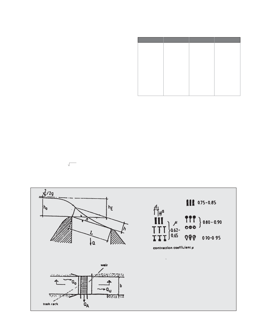
intake: QA=2/3 c µ b L 2gh
TABLE 3.4 x values for ß
ßX
0° 1.000
2° 0.980
4° 0.961
6° 0.944
8° 0.927
10° 0.910
12° 0.894
ß
14°
16°
18°
20°
22°
24°
26°
X
0.879
0.865
0.851
0.837
0.825
0.812
0.800
where:
QA= design discharge into the intake in m3/s
b = width of the bottom intake in m
L = length of the trashrack in m. In practice, it is
recommended that the trashrack length (L) be increased by
20%, i.e., L= 1.2 x Lcalculated . This will ensure that there will be
adequate flow when the trashrack is partially blocked by
wedged stones and branches.
h = 2/3 x hE
ho = Initial water depth in m in the river upstream of the intake.
hE = ho + vo2/2g.
Note that as can be seen in Figure 3.13 hE is actually the
initial water depth in the river plus the velocity head of the
Figure 3.13 Symbols used in the bottom intake equation.