CIVIL WORKS GUIDELINES FOR MICRO-HYDROPOWER IN NEPAL
25
the trashrack at the forebay. For side intakes, the function of
the trashrack is to stop boulders, cobbles, floating logs and
branches from entering the headrace. Coarse trashracks for
side intakes are not designed to exclude gravel and sediment.
This is the job of the gravel trap and the settling basin.
The size of the trashrack should be such that the water velocity
is approximately 0.6 m/s (a lower velocity is uneconomic,
whereas a high velocity tends to attract bedload and debris,
and results in increased headloss).
Since boulders can frequently impact the coarse trashrack, it
needs to be robust, i.e., thick steel sections should be used.
Depending on the length and width of the opening, nature of
the sediment load and the required flow, a clear spacing of
50 mm to 200 mm can be used. The side intake coarse trashrack
of the Galkot Micro-hydro Scheme is shown in Photograph 3.4.
the intake area (i.e., at the riverbank). If it appears that the
intake is at a flood plain or susceptible to damage from
boulders, then the orifice can be located downstream. In
such cases the canal upstream of the orifice and the intake
would be temporary and may require repair after every
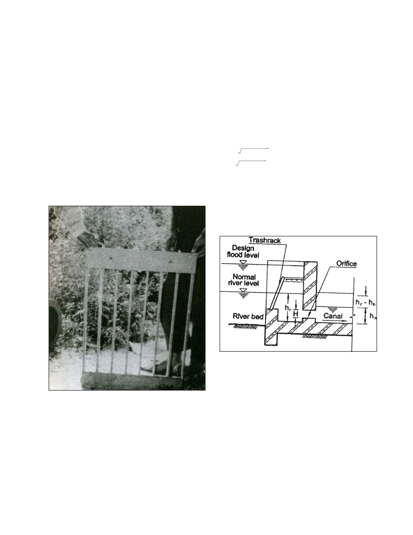
monsoon. An orifice is an opening (Figure 3.5) in the intake
from which the river water is conveyed towards the headrace.
The orifice allows the design flow to pass through it under
normal conditions (i.e., low flow) but restricts higher flows
during floods. The discharge through an orifice for
submerged condition is:
i = AC 2g (hr-hh)
V = C 2g (hr-hh)
where:
Q is the discharge through the orifice in m3/s
V is the velocity through the orifice
A is the area of orifice in m2
hr is the water level in the river next to the orifice relative to a
datum.
Figure 3.5 Slide intake
Photo 3.4 Coarse trashrack for 50 kw Galkot MHP, Baglung, Nepal.
65 mm * 10 mm flats at 75 mm centre. ( See Appendix C for the
drawing )
3.5.3 ORIFICE DESIGN
A side intake normally includes an orifice downstream of
the trashrack at the riverbank, through which water is
initially drawn into the headrace. Sometimes, the side
intake is just a continuation of the headrace canal up to the
riverbank. However, as far as practicable, an orifice should
be incorporated to limit excessive flows during floods. With
an intake that is just a continuation of the headrace canal to
the riverbank, excess flow cannot be controlled during floods.
Such excess flow can damage the headrace canal and other
structures downstream. However, the orifice need not be at
hh is the water level in the headrace canal measured from the
same datum as hr.
g is the acceleration due to gravity = 9.8 m/s2
C is the coefficient of discharge of the orifice and is dependent
on the shape of orifice. The value of C decreases with the
amount of turbulence induced by the intake. For a sharp edged
and roughly finished concrete or masonry orifice structure
this value is as low as 0.6 and for carefully finished aperture
it can be up to 0.8.
(hr - hh) will vary according to the discharge in the river since
a higher water level in the river will produce a greater head at
the orifice.
The maximum velocity for a well constructed
concrete/ masonry orifice is 3 m/s: if the velocity exceeds this