CIVIL WORKS GUIDELINES FOR MICRO-HYDROPOWER IN NEPAL
113
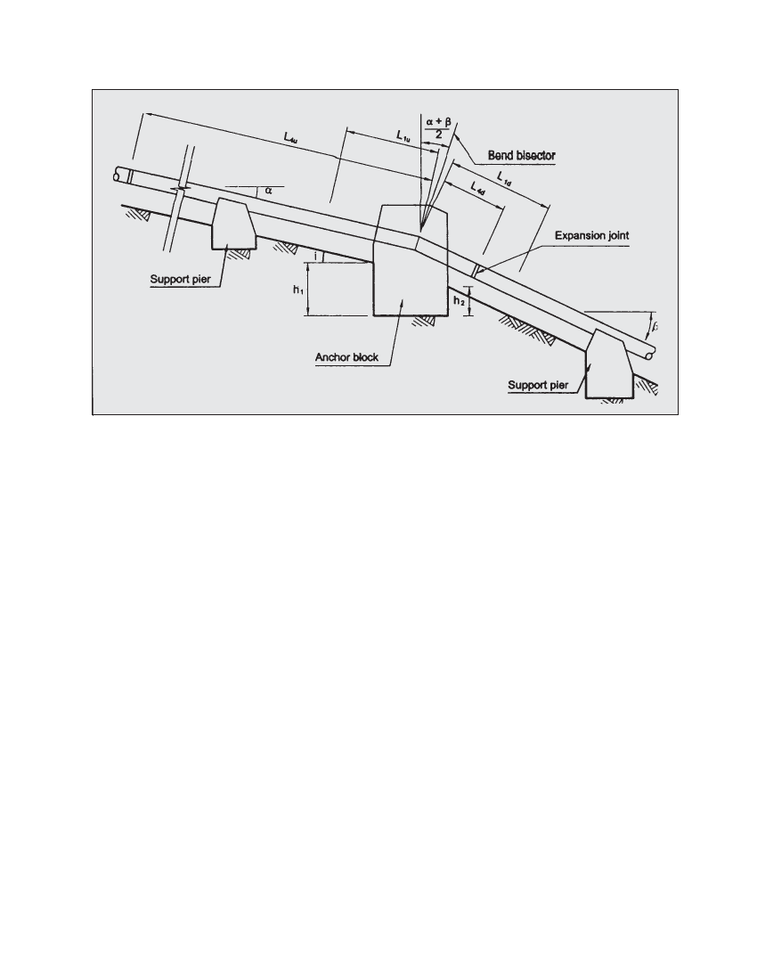
Figure 7.5 Distances and angles used in anchor block and support pier equation
7.4.2 DESCRIPTION OF FORCES
F1 - F1 is the component of the weight of pipe and enclosed
water perpendicular to the pipe alignment. If there is a bend
at the anchor, however, both the upstream and downstream
lengths of pipe contribute separately, each force perpendicular
to the centreline of the pipe segment which contributes to it.
F2-F2 is the frictional force of pipe on support piers. If the
penstock moves longitudinally over support piers, a friction
force on the pipe is created at each pier. A force “F2”, equal to
the sum of all these forces but opposite in direction, acts on
the anchor. This force exists only where one or more support
piers are located between the anchor block and an expansion
joint. For example, if an expansion joint is located immediately
downhill of the anchor, friction forces on the downhill length
of pipe will not be transmitted to the anchor block from that
side. The friction coefficient, f, depends on the material
against which the penstock slides and is as follows:
steel on concrete, f = 0.60
steel on steel, rusty plates, f = 0.50
steel on steel, greased plates or tar paper in between, f = 0.25
F3 - F3 is the force due to hydrostatic pressure within a bend.
The hydrostatic pressure at a bend creates a force which acts
outward for upward bends and inward if the bend is down-
ward. This is a major force which must be considered in
designing anchor blocks. However, the block size can be
significantly reduced if the bend angle (β - α) can be
minimised while fixing the penstock alignment.
F4 - F4 is the force due to the component of the weight of pipe
parallel to the pipe alignment. On a slope, the component of
the weight of the pipe which is parallel to the pipe tends to
pull it downhill and exerts a force on an anchor block. The
sections of pipe both upstream and downstream of an anchor
block may have to be considered. The lengths ‘L4u’ and ‘L4d’ in
the equation for the force “F4” acting on an anchor block are
the lengths of the upstream or downstream section of the
penstock which is actually to be held by that block. The
upstream section may begin at the forebay or, more usually, at
an expansion joint. The downstream section usually ends at
an expansion joint. If the expansion joint downstream of an
anchor block is located near the anchor, as it usually is, the
force arising from the weight of the downhill section of pipe
between the anchor and the joint is insignificant and is
usually neglected. Also, the anchor block will not experience
this force if the penstock is buried since the ground friction
will resist this force.
F5 - F5 is the force that is transmitted to the anchor block due
to thermally induced stresses in the absence of an expansion
joint. If an exposed section of a rigid pipe does not incorporate
an expansion joint, thermally induced stresses build up in
the pipe and act on the anchor block. The associated force
“F5” may push against the anchor block (with increasing
temperature) or pull the anchor block (with decreasing
temperature).
F6 - F6 is the force due to friction within the expansion joint.
To prevent leaking, the packing within an expansion joint
must be tightened sufficiently. However, this tightening also
makes it more difficult for the joint to accept any longitudinal
movement of the pipe. Friction between the packing and the
concentric sleeves in the expansion joint creates a force “F6”
which opposes any expansion or contraction of the pipe. This
force is dependent on pipe diameter, tightness of the packing