82 CIVIL WORKS GUIDELINES FOR MICRO-HYDROPOWER IN NEPAL
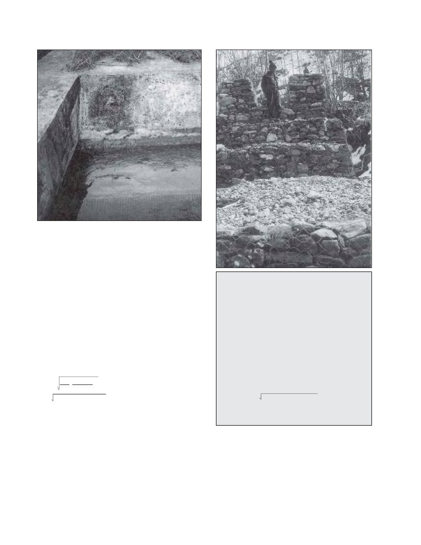
Photo 5.12 Submerged trashrack, Salleri Chialsa mini-hydro scheme
through the air intake pipe and into the penstock.
The required size of the air vent is given by:
d2 =Q or
F/E ( D / teffective )3
where:
d = internal diameter of air vent (mm)l
Q = maximum flow of air through vent (l/s)
= maximum flow of water through turbine
E = Young’s Modulus for the penstock (N/mm2, see Table
6.2)
D = Penstock diameter(mm)
teffective = effective penstock wall thickness at upper end
(mm) (refer to Section 6.6)
F = safety factor, 5 for buried pipe or 10 for exposed pipe.
dr = Q
( )F D 3
E teffective
5.5 Construction of water retaining
structures
Once the size of the gravel trap, settling basin and forebay
have been calculated, the type and dimensions of the walls
and floors need to be determined. For micro-hydro schemes,
stone masonry in cement mortar is generally the most
appropriate and economic option. The construction details
and procedures for this type of structure are as follows:
The ground should first be excavated according to the basin
shape and then be well compacted using a manual ram.
Since these are water retaining structures, 1:4 cement sand
mortar should be used for the walls and floors as discussed
Example 5.2 Sizing of air vent
Consider a 300 mm steel penstock of 3 mm wall thickness
connected to a turbine that can take 2501/s. The penstock
is above ground.
Q = 250 1/s
E = 2.0 x 10⁵ N/mm2 (from Table 6.2)
D = 300 mm
t = 3mm
teffective = 1.27 mm (from Section 6.6)
F = 10 for above ground pipe
Then d2 = 250 10 / 2x10⁵(300 / 1.27)3
Or, d = 80 mm, i.e. the minimum internal diameter of the air
vent should be 80 mm.
in Chapter 4.
The walls should be built such that they are a minimum
of 300 mm thick at the top and increase with depth as
shown in Figure 5.9. Note that in this figure, the wall
surface on the water retaining side is vertical. This
increases the stability of the structure since for a constant
depth the water pressure is larger than the soil pressure.