62 CIVIL WORKS GUIDELINES FOR MICRO-HYDROPOWER IN NEPAL
TABLE 4.3 Roughness value for different pipe materials
MATERIAL
ROUGHNESS VALUE, k (mm)
Smooth pipes
PVC.HDPE, MDPE, Glass fibre
0.06
Concrete
0.15
Mild steel
- Uncoated
- Galvanised
0.06
0.15
5. Check if the total head loss for the design flow is less than
the loss in head due to the pipe gradient (S) and that the
pipe profile is below the hydraulic grade line everywhere.
If not, repeat calculation with larger pipe diameter.
6. Determine the water level at the control structure
at the end of pipe such as the break pressure tank,
gravel trap or the settling basin. Allow 10% margin by
assuming that the total head loss is 10% higher than
calculated (i.e. water level is 10% lower than calculated).
This is to allow for uncertainties such as the wall losses
being higher than assumed.
7. Repeat calculations with higher submergence head
due to flood flows and calculate the corresponding
losses and pipe flow. The excess flow will have to be
spilled from a control structure (gravel trap, settling
basin etc.) at the end of the pipe.
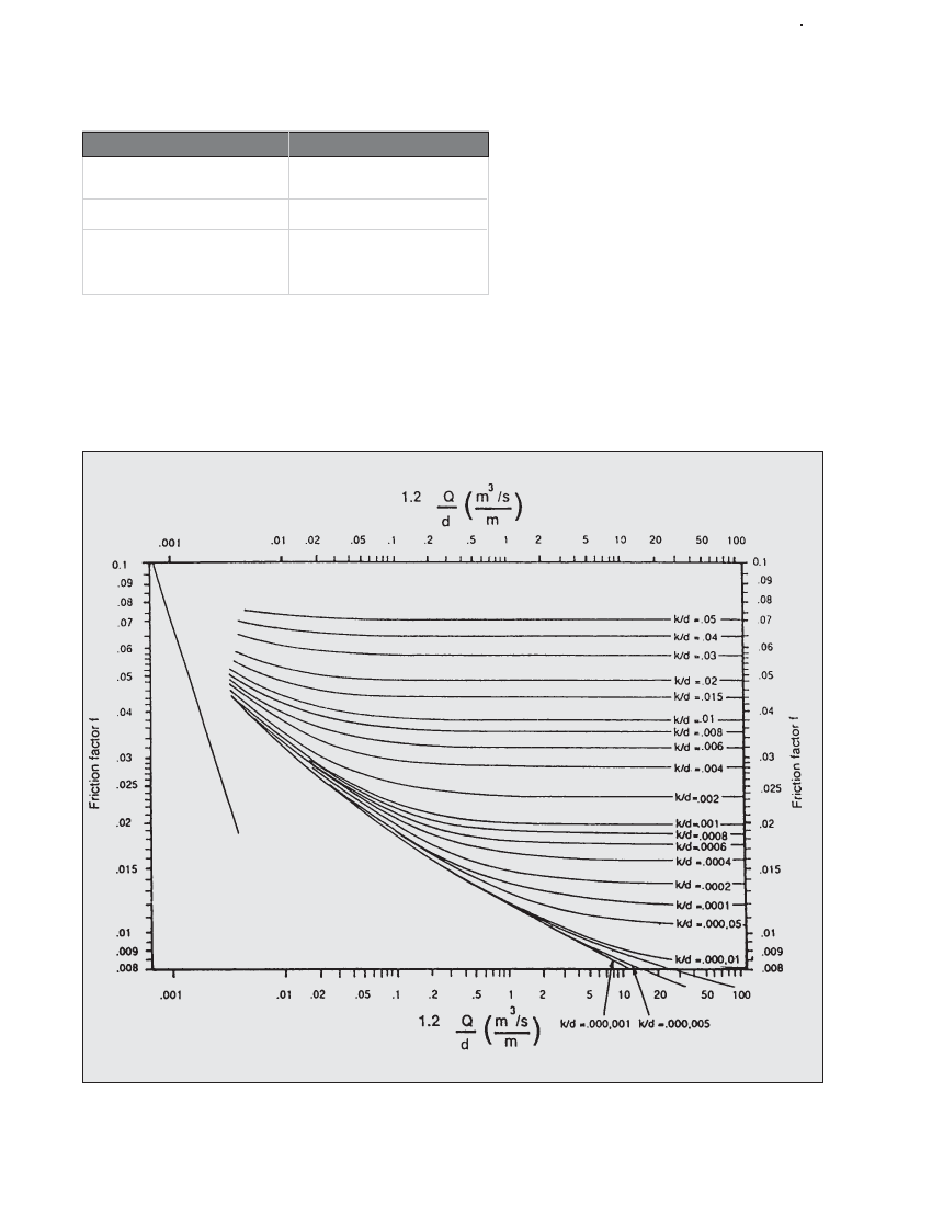
Figure 4.10 Moody chart