CIVIL WORKS GUIDELINES FOR MICRO-HYDROPOWER IN NEPAL
55
Design of spillway
Note that 2 conditions need to be checked as follows:
1. The spillway must be able to convey the entire flood flow of 48 l/s in case the headrace canal downstream gets
obstructed (ponding case).
2. The spillway should be able to spill the excess flow (480 l/s - 285 l/s) when there is no obstruction downstream.
The calculated maximum spillway length should be used in the design.
Calculations
Choose a broad crested weir with round edges profile, so C = 1.6
w
case 1:
Q
spillway
h
overtop
= 480 l/s
= 100 mm calculated earlier.
Now calculate the length of the spillway,
Lspillway = Qspillway / Cwx(hovertop)1.5
Lspillway = 0.480/1.6x(0.1)1.5 = 9.5 m
Case 2:
Qspillway = 480-285 = 0.1951/s
L = 2Q / C x(h )1.5
spillway
spillway w overtop
Lspillway = 2x0.195 /1.6x(0.1)1.5 = 7.7m
Therefore a spillway length of 9.5 m is required for the above canal (Case1)
4.5 Crossings
Sometimes the headrace or the penstock alignment may need
to cross gullies and small streams. Crossings are such structures
that convey the flow over streams, gullies or across unstable
terrain subject to landslides and erosion.
The Galkot crossing with a spillway was shown in Photograph
4.10. This is a 1.2 m long aqueduct that is constructed from
Photo 4.13 HDPE pipes provide an overflow from a timber
channel (Mhapung)
reinforced concrete. Its size and slope are similar to the
upstream headrace canal. In micro-hydro schemes, reinforced
concrete crossings may be feasible if the length is short. Such
structures are expensive and complicated for longer lengths.
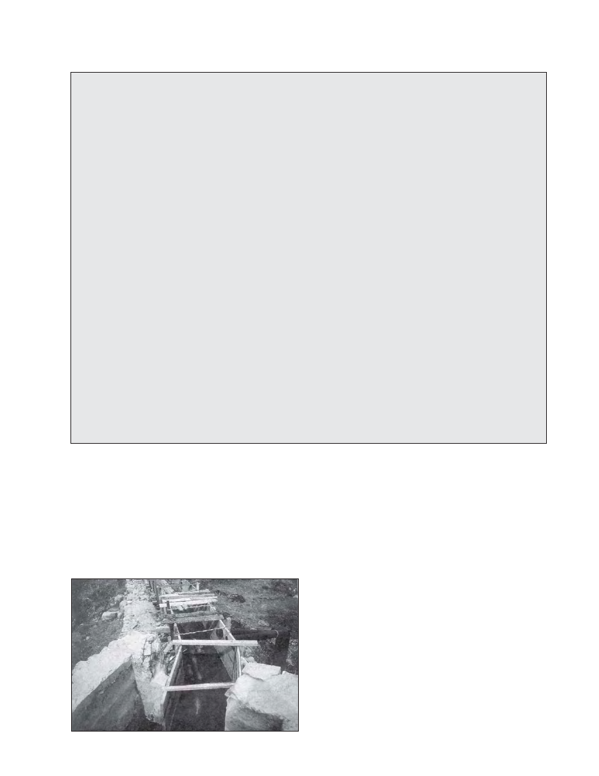
The Jhankre mini-hydro penstock crossing can be seen in
Photograph 4.14. In this case the penstock alignment had to
traverse a 12.6 m wide gully. This gully is active only in the
monsoon and at other times it is dry. A series of masonry
walls were designed to support the penstock (similar to the
support piers) along the gully. All of these walls rest on a
continuous foundation pad. During the monsoon, the surface
runoff flows between the walls.
Photograph 4.15 shows the Ghandruk crossing. The 50 kW
Ghandruk micro-hydro scheme has a long HDPE headrace
pipe (see Box 4.6) and at one location, the alignment had to
cross a gully. As can be seen in the photograph, a mild steel
pipe was used for the crossing with another vertical pipe
supporting it.
Apart from the types of crossings discussed above, inverted
siphons are also sometimes used across gullies. Inverted