CIVIL WORKS GUIDELINES FOR MICRO-HYDROPOWER IN NEPAL
139
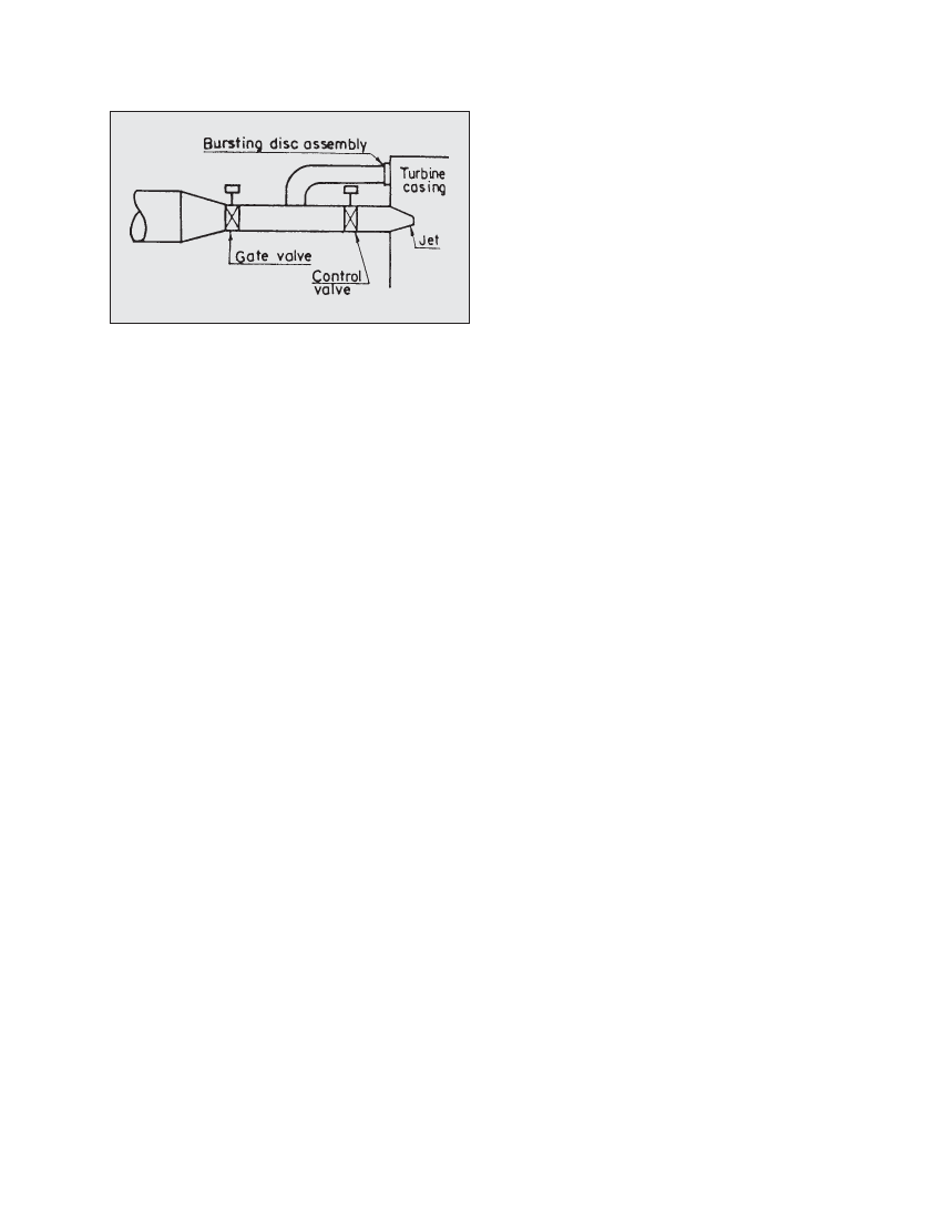
Figure 10.2 Proposed arrangement for bursting disc installation in
micro-hydro schemes
More information on the applicability of bursting discs for
micro-hydro schemes can be obtained from Dulas Limited
(same address as above).
Information on commercial bursting discs can also be obtained
from the following manufacturer:
IMI Marston Limited
Wobaston Road, Fordhouses,
Wolverhampton WV106QJ
England, UK
Fax: +44 (0) 1902 397792
10.5 Flexible steel support pier for Jharkot
micro-hydro
The 36 kW Jharkot micro-hydro scheme is located in Mustang
District, Nepal. This is a community owned scheme and is
managed by the Jharkot Electrification Committee. Practical
Action in Nepal has been involved in providing technical
support for refurbishment work of this scheme for some time.
Similar to other areas of Mustang, the topography of the project
area consists of fragile and unstable slopes and is prone to
landslides. The intake and the initial headrace canal have
been damaged frequently by landslides and floods. Although
the slope along the penstock alignment is relatively stable
compared to the intake area, it is weak and also prone to
landslides. The existing masonry support piers started sinking
due to their own weight as well as the weight of the penstock
pipe and the water inside it. Hence, the penstock (flange
connected) started to sag at various places. As part of the
preparation of this text, a pilot project was carried out to design
and install steel support piers for the Jharkot scheme with
assistance from Mr. Shyam Raj Pradhan of NYSE. The design
criteria were as follows:
The support pier had to be light, to minimise self weight.
It had to be fabricated using parts that could be carried by
porters or mules. Jharkot is about half a day’s walk from the
district airport and 5 days’ walk from the nearest roadhead.
The design had to allow for the sinking of the foundation.
In case of sinking of the ground below the foundations, the
piers should not pull the penstock pipe down along with it.
The design of the support pier and the foundation are shown
in Figures 10.3 and 10.4 respectively. The total weight of a 2
m support pier is 60 kg (excluding the foundation work)
whereas a masonry pier of similar height would weigh 4000
kg. Note that such support piers should be installed
perpendicular to the penstock alignment (not vertically) since
they are only resisting force Fj (see Chapter 7). The top section
of the pier consists of a channel which is pin connected to two
legs that have turnbuckles. The penstock pipe rests on the
channel and the pin connection allows the channel some
rotation such that it is perpendicular to the penstock alignment.
Two holes have been provided on the channel to clamp the
penstock with a 12 mm diameter bar. The turnbuckles can be
adjusted to fine tune the height of the support piers (up to
300 mm) during installation and in case the foundation sinks
in the future. The bottom of the turnbuckles (40 mm rods) fit
inside a hollow pipe as shown in Figure 10.3. In case the
ground beneath the foundation sinks, the support pier
structure below the turnbuckles drops down along with the
foundation and only the top part (up to the turnbuckle legs)
hangs with the penstock. Hence the penstock pipe is not
dragged down with the pier in case of sinking. The bottom
part of the pier consists of angles which are bolted back to
back (Figure 10.3). Bolt holes at a distance of 150 mm are
provided for coarse adjustment of the pier. The bottom angles
are pin connected to the foundation so that the moments due
to thermal expansion of the penstock pipe are not taken by
the support pier or the foundation.
During installation as well as later in case the foundation sinks,
coarse adjustment can be made using the bolt holes of the bottom
angles and then fine tuned using the turnbuckles at the top. The
top and bottom parts of the pier have fixed heights. The length of
the middle portion (angles bolted to channels) is varied such
that the total pier height is equal to the required height. Note
that this support pier can be dismantled such that there are 12
individual pieces (including the 12 mm stirrup bar to connect to
the penstock). 18 support piers ranging from 1.0 m to 2.6 m
height have been fabricated based on this design. To ensure
that the support pier would function well, one (2.5 m total height)
was tested at the manufacturer’s workshop (NYSE) as shown in
Photographs 10.7 and 10.8. About 500 kg of axial load
(maximum compressive load expected on the pier) was applied
on the pier. There was no observable effect on the pier
(deformation or deflection of angles) during the test of about 2
hours. It was even possible to raise the height of the pier by
rotating the turnbuckles with the full test load of 500 kg.
As of July 1998, all 18 support piers have been installed at the
Jharkot scheme. Their performance is currently being monitored.