108 CIVIL WORKS GUIDELINES FOR MICRO-HYDROPOWER IN NEPAL
Notes:
1. Applies only to steel penstocks welded or flanged to British Standard (minimum flange thickness = 16 mm). In other cases
use one support pier for each individual pipe length, with the pier in the middle.
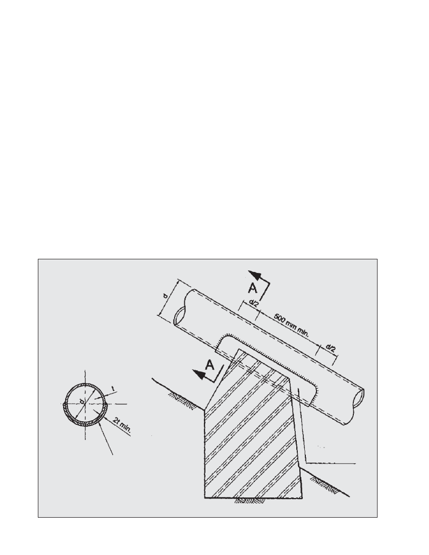
2. Wear plates to be of some thickness as pipe wall , and weilded an all edges, covering bottom 1800 of pipe. The length should
be enough to extend at least 0.5 times the pipe diameter beyond each side of the support pier. See figure 7.3
3. For the calculation of teffective refer to Section 6.6.
4. Interpalate between the above values for intermediate pipe diameters, wall thickness or steel grades.
7.3.2 CONSTRUCTION OF SUPPORT PIERS
Support piers are generally constructed out of stone masonry
in 1:4 cement mortar. Dressed stone should be used for the
outside surfaces of the pier. A 140° bearing area from the
centre of the penstock diameter should be provided to support
the penstock pipe as shown in Figure 7.4. Placing a steel
saddle plate above the support pier where the penstock pipe
rests along with a 3 mm thick tar paper as shown in Figure 7.4
minimises frictional effects and increases the useful life of
the pipe. C-clamps may also be provided to protect the pipe
from vandalism and a sideways movement, but there must
be a gap between the surface of the pipe and the C-clamp, so
that axial forces are not transferred to the support pier. Stone
masonry support piers with C-clamps can be seen in Photograph
7.5.Wooden support piers have occasionally been used in
micro-hydro schemes, as can be seen in Photograph 7.7.
However, wood is generally expensive and also requires
frequent maintenance such as painting.
Steel support piers can also be used as an alternative to stone
masonry, especially at sites where cement is expensive or the
soil is weak in bearing. An example of steel support piers is
included in Chapter 10 (Innovations).
Figure 7.3 Arrangement of wear plate at support pier