CIVIL WORKS GUIDELINES FOR MICRO-HYDROPOWER IN NEPAL
137
iv. During steady state when the turbine was under
operation, the water depth in the chamber remained
below the toe of the screen. Thus, the submergence
depth set initially seemed to be adequate.
v. The water level inside the forebay chamber decreased
by 400 mm compared to the previous case, thus
decreasing the gross head by about 0.7 percent.
Although, the Cha Khola plant has faced intermittent problems
with the generating equipment, to date the screen is
performing satisfactorily.
10.3 De-beader for HDPE pipes
As discussed in Chapter 4 (Box 4.7), HDPE pipes are joined by
heat welding which melts and fuses the ends together. This
leads to raised “beads” on the inside and outside of the pipe
as shown in Photograph 10.2. The external bead is not a
problem but the internal bead promotes blockages and
significant head loss. An effective debeader would reduce
the roughness value for HDPE from 0.06 mm (Table 4.3) to
0.03 mm.
A “debeader” tool has been designed (for IT Nepal) to remove
the internal beads from HDPE pipes while the joints are still
hot (i.e., hot debeading). This equipment has been designed
to remove beads for pipe diameters up to 250 mm. It is still in
the experimental phase and requires some development for
use in the field.
As shown in Photograph 10.3, the debeader consists of a
mild steel shaft with a sleeve on which a bush spring loaded
to a locking collar (via an Alien key) is placed. There are three
hardened steel blades (cutter arms) that are pin connected by
rectangular steel bars to the bush. By unlocking the bush the
connecting pin can slid up the sleeve to increase the cutting
diameter.
Debeading with this tool is done by first unlocking the bush
so that the tool can fit inside the pipe. A mild steel rod with a
handle is connected to the debeader such that the handle
sticks out of the pipe. The rod is supported by a number of
mild steel discs inside the pipe (smaller than the HDPE pipe
diameter) for lateral stability. The de-beader is then placed
inside of the pipe such that it is about 100 mm in front of the
proposed joint. The radius of the cutting arms are then
arranged by sliding the bush such that the blades are in
contact with the inside pipe surface. Once the blades snugly
fit on the pipe surface, there is a clicking sound indicating
that the cutting arms have been locked. As soon as the two
pipe ends are joined by heat welding as discussed in Chapter
4, the debeader is pushed forward till the blades come in
contact with the beads. The handle is then turned and the
debeader is pushed forward which removes the bead.
This de-beader was tested at Nepal Yantra Shala Energy,
Kathmandu, on a 200 mm pipe as shown in Photograph 10.4.
Debeading was tried on a joint about 2 m from one end of the
pipe. The test was partially successful. It was not possible to
remove the entire strip of the bead. Part of the bead and some
thin strands were left on the joint, as can be seen in
Photograph 10.4.
The following observations were made in the workshop:
The major constraint was that the radius of the cutter blades
is fixed and the blades do not work equally well on all pipe
diameters within the range.
If debeading is not started immediately after the pipes are
joined (i.e. within 30 seconds), the beads cannot be
removed.
The turning of the handle and pushing of the de-beader
has to be controlled. A sudden jerk pushes the de-beader
beyond the joint.
The debeading process is also hampered if the pipe ends
are not totally circular.
Photo10.4 HDPE pipe joint de-beaded using the de-beader
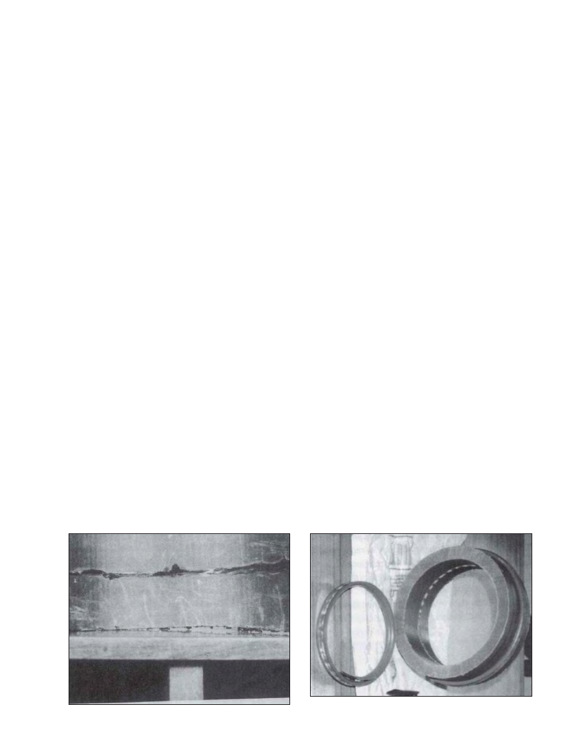
Photo10.5 HDPE pipe joint de-beaded using a commercial de-beader.
The small ring in front of the pipe section is the bead.