130 CIVIL WORKS GUIDELINES FOR MICRO-HYDROPOWER IN NEPAL
9.3 Bio-engineering works
All engineering measures such as retaining walls and check
dams should be well supplemented with bio-engineering
measures as far as practicable.
Planting grass or shrubs on the freshly cut hill or the landslide
area are examples of bio-engineering measures. Fast growing,
deep rooted and dense cover type of vegetation that is appropriate
to the local environment should be used for such purposes.
Only deep-rooted trees should be used for bio-engineering
purposes, and they should not be planted so close to canals or
structures that their roots could cause piping or structural damage.
At least 3 metres clearance is recommended. Fast growing trees
that do not have intense root systems should be avoided since
they may fall due to their own weight during storms.
Once the slopes have been stabilised, care should be taken to
ensure that there is no further overgrazing.
9.4 Retaining structures
Retaining walls are structures that support the backfill and
surcharge load from the additional canal width or platform
over the walls in hill sections. Though the per metre cost of
canal construction requiring retaining walls is more than
constructing the same length by cutting inside the hill, the
use of retaining walls sometimes becomes essential.
The most common types of retaining wall used in micro-hydro
schemes are gravity walls of gabions or cement masonry. These
depend on the mass of the structure to resist overturning.
Their design depends on the wall density, soil parameters,
drainage and loading conditions, typically resulting in a base
width of 0.40 to 0.65 times the height. The designs shown in
Figures 9.1 and 9.2 are therefore safe, but conservative in
many conditions.
For high or long walls it will be economical to design for the
specific site conditions. Site specific designs should also be
made where the backfill is inclined rather than horizontal.
The walls should be checked for overturning, sliding and
bearing pressure, as described for anchor blocks in Chapter 7.
Alternatively refer to standard civil engineering texts such as
Ref. 7. (The unit weight of filled gabions is 14-18 kN/m3,
depending on the unit weight of the rock fill and assuming
30-35% voids).
Wall foundations must be deep enough to be safe against
erosion: normally at least 0.5 m below ground level, but
see Section 3.8 for river works. Lined toe drains may be
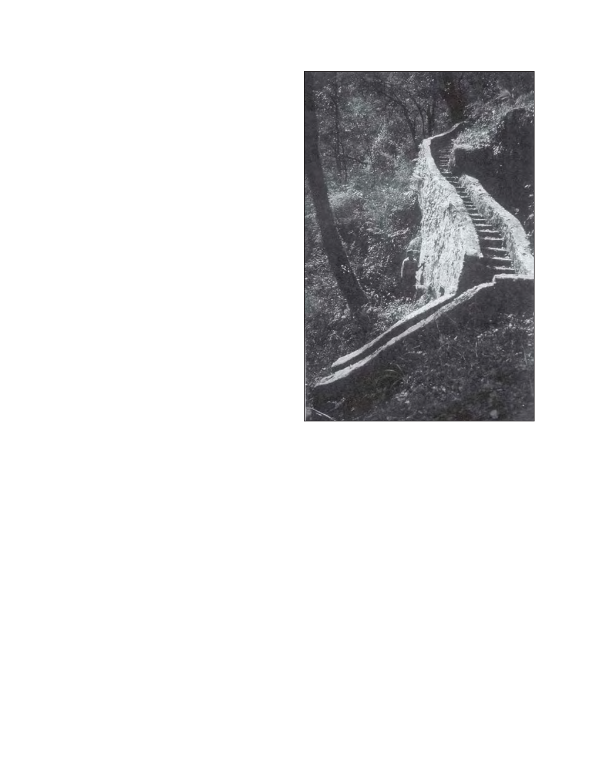
Photo 9.2 Masonry steps for energy dissipation and control of
spillway water. Although costly, elaborate control is essential
where slopes are vulnerable to erosion (Siklis)
used in erodible areas to carry seepage water safely away
from the wall foundation.
Gabion retaining walls should be constructed with an
inclination of 10%, see Figure 9.1. Where gabions are to be
built on sand or fine soils, a layer of filter cloth should be
placed between the foundation and the gabions. The gabion
boxes should be laced together along all edges and stretched
before filling with rock. The rock should be packed with the
minimum of voids.
Stone masonry walls can be constructed in 1:4 cement/ sand
mortar as shown in Figure 9.2. Such walls are suitable for
retained heights of up to 2 to 3 m. The slope of the front face
may be steepened if necessary, provided that the base width
is maintained. The rear face of the wall should be left rough
to increase friction with the backfill. Weepholes must be
provided to relieve water pressure behind the wall, and their
mouths should be protected with carefully placed stones.
Backfill behind the wall should be freedraining gravel or stones;
if the retained soil is fine, a filter cloth should be placed as
shown to prevent the soil particles blocking the drainage.