Carbon capture and storage
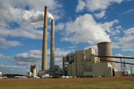
Carbon capture and storage (CCS), refers to a set of technologies designed to reduce carbon dioxide (CO2) emissions from large-point sources such as coal-fired power plants to mitigate greenhouse gas production. CCS technology (or sequestration) involves capturing CO2 and then storing the carbon in a reservoir other than the atmosphere (Earth's atmosphere), instead of allowing it to be released into the atmosphere where its accumulation contributes to climate alteration,. This article covers only CCS and not other types of carbon sequestration activities whereby CO2 is removed from the atmosphere and stored in vegetation, soils, or oceans. Forests and agricultural lands store carbon in the natural environment, and the world’s oceans exchange massive amounts of CO2 from the atmosphere through natural processes.
An integrated CCS system would include three main steps:te
- capturing and separating CO2;
- compressing and transporting the captured CO2 to the sequestration site; and
- sequestering CO2 in geological reservoirs or in the oceans
Electricity-generating plants are among the most likely initial candidates for capture, separation, and storage, or reuse of CO2 because they are predominantly large, single point sources for emissions and contribute the largest proportion of CO2 emissions compared to other types of fossil fuel use in many countries, including the United States (See Table 1.) Large industrial facilities, such as cement-manufacturing, ethanol, or hydrogen production plants, that produce large quantities of CO2 as part of the industrial process are also good candidates for CO2 capture and storage.
from Combustion of Fossil Fuels
|
Sources |
CO2 Emissionsa |
Percent of Totalb |
|
Electricity generation |
2,273.3 |
41% |
|
Transportation |
1,856.0 |
33% |
|
Industrial |
862.2 |
15% |
|
Residential |
326.5 |
6% |
|
Commercial |
210.1 |
4% |
|
Total |
5,583.0 |
100% |
Source: U.S. Environmental Protection Agency (EPA), Inventory of U.S. Greenhouse Emissions and Sinks: 1990-2006, Table ES-3.
a. CO2 emissions in millions of metric tons for 2006; excludes emissions from U.S. territories.
b. Total does not sum to 100% because of rounding.
Several different categories of strategies for storing carbon are possible and have been proposed; these include storing carbon in terrestrial ecosystems, the oceans, and underground in geologic formations. Terrestrial carbon storage refers primarily to biological carbon sequestration in the biosphere relying on the photosynthetic process of capturing and converting atmospheric carbon dioxide into organic carbon. Ocean storage generally refers to the injection of captured CO2 directly into the oceans but also includes other mechanisms of enhancing oceanic uptake of carbon. Geologic carbon storage refers to the injection of captured CO2 into underground, naturally occurring geologic reservoirs that will trap the gas to prevent it from re-entering the atmosphere. Another proposed approach often referred to as mineral carbonation involves chemical reactions that transform the carbon in gas-phase CO2 into solid-phase carbonate minerals. Among these different carbon storage approaches, geologic storage has emerged as the method with the greatest potential for large-scale CO2 emissions reductions in the near term.
A complete CCS system involving geologic carbon storage includes four basic steps with different technologies required for each step: (1) capture the CO2 from a power plant or other concentrated stream; (2) transport the CO2 gas from the capture location to an appropriate storage location; (3) inject the CO2 gas into an underground reservoir; and (4) monitor the injected CO2 to verify its storage. Technologies that are commercially-used in other sectors are currently available for each of these components. CO2 capture technology is already widely used in ammonia production and several other industrial manufacturing processes as well as oil refining and gas processing. CO2 gas has been transported through pipelines and injected underground for decades, most notably in West Texas where it is used to enhance oil recovery (EOR) of declining-production wells. Some 3-4 million tons of CO2 per year is currently successfully stored underground at several locations, including Sleipner in the North Sea, Weyburn in Saskatchewan, Canada, and In Salah in Algeria. Technologies to monitor the carbon dioxide and verify its storage are also available. The integration and the scaling-up of the existing technologies to capture, transport, and store CO2 emitted from a full-scale power plant, however, has not yet been demonstrated, although this is the goal of the US Department of Energy’s FutureGen project.
The concept of engineering systems to deliberately capture and store CO2 has evolved in the past twenty years from a relatively obscure idea to an increasingly recognized set of potential climate change mitigation options. While the technical feasibility of CCS involving underground storage in geologic formations has been demonstrated in other applications and several demonstration projects, this technology is unlikely to be used widely until regulations on carbon emissions are instituted so that reducing carbon dioxide emissions into the atmosphere provides an economic benefit that will offset the cost of implementing the technology. Although studies on the risks associated with injecting CO2 underground have found minimal concerns, widespread of adoption of CCS technology could also be limited by public acceptance due to the novelty of the concept as well as by uncertainties resulting from the lack of demonstrated full-scale integration of the technology.
Contents
Capturing CO2
The first step in CCS is to capture CO2 at the source and produce a concentrated stream for transport and storage. Currently, three main approaches are available to capture CO2 from large scale industrial facilities or power plants: (1) post-combustion capture, (2) pre-combustion capture, and (3) oxy-fuel combustion capture. For power plants, current commercial CO2 capture systems could operate at 85%-95% capture efficiency. Techniques for capturing CO2 have not yet been applied to large power plants (e.g., 500 megawatts or more).
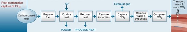
Post-Combustion Capture
This process involves extracting CO2 from the flue gas following combustion of fossil fuels or biomass. Several commercially available technologies, some involving absorption using chemical solvents, can in principle be used to capture large quantities of CO2 from flue gases. U.S. commercial electricity-generating plants currently do not capture large volumes of CO2 because they are not required to and there are no economic incentives to do so. Nevertheless, the post-combustion capture process includes proven technologies that are commercially available today. Figure 1 shows a simplified illustration of this process.
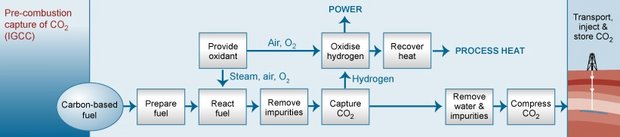
Pre-Combustion Capture
This process separates CO2 from the fuel by combining it with air and/or steam to produce hydrogen for combustion and a separate CO2 stream that could be stored. The most common technologies today use steam reforming, in which steam is employed to extract hydrogen from natural gas. In the absence of a requirement or economic incentives, pre-combustion technologies have not been used for power systems, such as natural gas combined-cycle power plants. Figure 2 shows a simplified illustration of this process. Pre-combustion capture of CO2 is viewed by some as a necessary requirement for coal-to-liquid fuel processes, whereby coal can be converted through a catalyzed chemical reaction to a variety of liquid hydrocarbons. Concerns have been raised because the coal-to-liquid process releases CO2, and the end product—the liquid fuel itself—further releases CO2 when combusted. Precombustion capture during the coal-to-liquid process would reduce the total amount of CO2 emitted, although CO2 would still be released during combustion of the liquid fuel used for transportation or electricity generation.
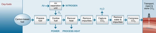
Oxy-Fuel Combustion Capture
This process uses oxygen instead of air for combustion and produces a flue gas that is mostly CO2 and water, which are easily separable, after which the CO2 can be compressed, transported, and stored. This technique is still considered developmental, in part because temperatures of pure oxygen combustion (about 3,500o Celsius) are far too high for typical power plant materials. Figure 3 shows a simplified illustration of this process.
Application of these technologies to power plants generating several hundred megawatts of electricity has not yet been demonstrated. However, The 2_en/CO2_en/Gemeinsame_Inhalte/DOCUMENT/388963CO2x/401837CO2x/P0277108.pdf. Schwarze-Pumpe 30 MW oxy-fuel pilot plant in Germany has been operating since mid-2008. The captured CO2 will be used for enhanced gas recovery at a nearby natural gas field.
Up to 80% of the total costs for CCS may be associated with the capture phase of the CCS process.
Transportation
Pipelines are the most common method for transporting CO2 in the United States. Currently, over 5,800 kilometers (about 3,600 miles) of pipeline transport CO2 in the United States, predominately to oil and gas fields, where it is used for enhanced oil recovery (EOR). Transporting CO2 in pipelines is similar to transporting petroleum products like natural gas and oil; it requires attention to design, monitoring for leaks, and protection against overpressure, especially in populated areas.
Using ships may be feasible when CO2 needs to be transported over large distances or overseas. Ships transport CO2 today, but at a small scale because of limited demand. Liquefied natural gas, propane, and butane are routinely shipped by marine tankers on a large scale worldwide. Rail cars and trucks can also transport CO2, but this mode would probably be uneconomical for large-scale CCS operations.
Costs for pipeline transport vary, depending on construction, operation and maintenance, and other factors, including right-of-way costs, regulatory fees, and more. The quantity and distance transported will mostly determine costs, which will also depend on whether the pipeline is onshore or offshore, the level of congestion along the route, and whether mountains, large rivers,or frozen ground are encountered. Shipping costs are unknown in any detail, however, because no large-scale CO2 transport system (in millions of metric tons of CO2 per year, for example) is operating. Ship costs might be lower than pipeline transport for distances greater than 1,000 kilometers and for less than a few million metric tons of CO2 (MtCO2) transported per year.
Even though regional CO2 pipeline networks currently operate in the United States for enhanced oil recovery (EOR), developing a more expansive network for CCS could pose numerous regulatory and economic challenges. Some of these include questions about pipeline network requirements, economic regulation, utility cost recovery, regulatory classification of CO2 itself, and pipeline safety.
Sequestration in Geological Formations
Three main types of geological formations are being considered for carbon sequestration: (1) depleted oil and gas reservoirs, (2) deep saline reservoirs, and (3) unmineable coal seams. In each case, CO2 would be injected, in a dense form, below ground into a porous rock formation that holds or previously held fluids. By injecting CO2 below 800 meters in a typical reservoir, the pressure induces CO2 to become supercritical—a relatively dense liquid—and thus less likely to migrate out of the geological formation. Injecting CO2 into deep geological formations uses existing technologies that have been primarily developed by and used for the oil and gas industry, and that could potentially be adapted for long-term storage and monitoring of CO2. Other underground injection applications in practice today, such as natural gas storage, deep injection of liquid wastes, and subsurface disposal of oil-field brines, can also provide information for sequestering CO2 in geological formations.
Sedimentary basins refer to natural large-scale depressions in the Earth’s surface that are filled with sediments and fluids and are therefore potential reservoirs for CO2 storage. The storage capacity for CO2 storage in geological formations is potentially huge if all the sedimentary basins in the world are considered. The suitability of any particular site, however, depends on many factors including proximity to CO2 sources and other reservoir-specific qualities like porosity, permeability, and potential for leakage.
Oil and Gas Reservoirs
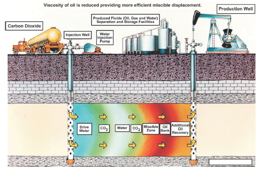
Pumping CO2 into oil and gas reservoirs to boost production (enhanced oil recovery, or EOR) is practiced in the petroleum industry today. The United States is a world leader in this technology and injects approximately 48 MtCO2 underground each year to help recover oil and gas resources. (see Figure 4.) Carbon dioxide can be stored onshore or offshore; to date, most CO2 projects associated with EOR are onshore, with the bulk of U.S. activities in west Texas. The advantage of using this technique for long-term CO2 storage is that sequestration costs can be partially offset by revenues from oil and gas production. Carbon dioxide can also be injected into oil and gas reservoirs that are completely depleted, which would serve the purpose of long-term sequestration, but without any offsetting benefit from oil and gas production.
The In Salah and Weyburn Projects
The In Salah Project in Algeria is the world’s first large-scale effort to store CO2 in a natural gas reservoir. At In Salah, CO2 is separated from the produced natural gas and then reinjected into the same formation. Approximately 17 MtCO2 are planned to be captured and stored over the lifetime of the project.
The Weyburn Project in south-central Canada uses CO2 produced from a coal gasification plant in North Dakota for EOR, injecting up to 5,000 tCO2 per day into the formation and recovering oil. Approximately 20 MtCO2 are expected to remain in the formation over the lifetime of the project.
Advantages and Disadvantages
Depleted or abandoned oil and gas fields, especially in the United States, are considered prime candidates for CO2 storage for several reasons:
- oil and gas originally trapped did not escape for millions of years, demonstrating the structural integrity of the reservoir;
- extensive studies have typically characterized the geology of the reservoir;
- computer models have often been developed to understand how hydrocarbons move in the reservoir, and the models could be applied to predicting how CO2 could move; and,
- infrastructure and wells from oil and gas extraction may be in place and might be used for handling CO2 storage.
Some of these features could also be disadvantages to CO2 sequestration. Wells that penetrate from the surface to the reservoir could be conduits for CO2 release if they are not plugged properly. Care must be taken not to overpressure the reservoir during CO2 injection, which could fracture the caprock—the part of the formation that formed a seal to trap oil and gas—and subsequently allow CO2 to escape. Also, shallow oil and gas fields (those less than 800 meters deep, for example) may be unsuitable because CO2 may form a gas instead of a denser liquid and could escape to the surface more easily.
Deep Saline Reservoirs
Some rocks in sedimentary basins are saturated with brines or brackish water unsuitable for agriculture or drinking. As with oil and gas, deep saline reservoirs can be found onshore and offshore; in fact, they are often part of oil and gas reservoirs and share many characteristics. The oil industry routinely injects brines recovered during oil production into saline reservoirs for disposal. Using saline reservoirs for CO2 sequestration has several advantages: (1) they are more widespread in the United States than oil and gas reservoirs and thus have greater probability of being close to large point sources of CO2; and (2) saline reservoirs have potentially the largest reservoir capacity of the three types of geologic formations.
The Sleipner Project
The Sleipner Project in the North Sea is the first commercial-scale operation for sequestering CO2 in a deep saline reservoir. The Sleipner project has been operating since 1996, and it injects and stores approximately 2,800 tCO2 per day, or about 1 MtCO2 per year. Carbon dioxide is separated from natural gas production at the nearby Sleipner West Gas Field, compressed, and then injected 800 meters below the seabed of the North Sea into the Utsira formation, a sandstone reservoir 200-250 meters (650-820 feet) thick containing saline fluids. Monitoring has indicated the CO2 has not leaked from the saline reservoir, and computer simulations suggest that the CO2 will eventually dissolve into the saline water, reducing the potential for leakage in the future.
Large CO2 sequestration projects, similar to Sleipner, are being planned in western Australia (the Gorgon Project) and in the Barents Sea (the Snohvit Project), that would inject 10,000 and 2,000 tCO2 per day respectively, when at full capacity. Similar to the Sleipner operation, both projects plan to strip CO2 from produced natural gas and inject it into deep saline formations for permanent storage.
Advantages and Disadvantages
Although deep saline reservoirs have huge potential capacity to store CO2, estimates of lower and upper capacities vary greatly, reflecting a high degree of uncertainty in how to measure storage capacity. Actual storage capacity may have to be determined on a case-by-case basis.
In addition, some studies have pointed out potential problems with maintaining the integrity of the reservoir because of chemical reactions following CO2 injection. Injecting CO2 can acidify (lower the pH of) the fluids in the reservoir, dissolving minerals such as calcium carbonate, and possibly increasing permeability. Increased permeability could allow CO2-rich fluids to escape the reservoir along new pathways and contaminate aquifers used for drinking water.
In an October 2004 experiment, researchers injected 1,600 tCO2 1,500 meters deep into the Frio Formation—a saline reservoir containing oil and gas—along the Gulf Coast near Dayton, TX, to test its performance for CO2 sequestration and storage. Test results indicated that calcium carbonate and other minerals rapidly dissolved following injection of the CO2. The researchers also measured increased concentrations of iron and manganese in the reservoir fluids, suggesting that the dissolved minerals had high concentrations of those metals. The results raised the possibility that toxic metals and other compounds might be liberated if CO2 injection dissolved minerals that held high concentrations of those substances.
Another concern is whether the injected fluids, with pH lowered by CO2, would dissolve cement used to seal the injection wells that pierce the formation from the ground surface. Leaky injection wells could then also become pathways for CO2-rich fluids to migrate out of the saline formation and contaminate fresher groundwater above. Approximately six months after the injection experiment at the Dayton site, however, researchers did not detect any leakage upwards into the overlying formation, suggesting that the integrity of the saline reservoir formation remained intact at that time.
Preliminary results from a second injection test in the Frio Formation appear to replicate results from the first experiment, indicating that the integrity of the saline reservoir formation remained intact, and that the researchers could detect migration of the CO2-rich plume from the injection point to the observation well in the target zone. These results suggest to the researchers that they have the data and experimental tools to move to the next, larger-scale, phase of CO2 injection experiments.
Unminable Coal Seams
According to DOE, nearly 90% of U.S. coal resources are not mineable with current technology, because the coal beds are not thick enough, the beds are too deep, or the structural integrity of the coal bed (coal seam) is inadequate for mining. Even if they cannot be mined, coal beds are commonly permeable and can trap gases, such as methane, which can be extracted (a resource known as coal bed methane, or CBM). Methane and other gases are physically bound (adsorbed) to the coal. Studies indicate that CO2 binds even more tightly to coal than methane. Carbon dioxide injected into permeable coal seams could displace methane, which could be recovered by wells and brought to the surface, providing a source of revenue to offset the costs of CO2 injection.
Advantages and Disadvantages
Unmineable coal seam injection projects would need to assess several factors in addition to the potential for CBM extraction. These include depth, permeability, coal bed geometry (a few thick seams, not several thin seams), lateral continuity and vertical isolation (less potential for upward leakage), and other considerations. Once CO2 is injected into a coal seam, it would likely remain there unless the seam is depressurized or the coal is mined. Also, many unmineable coal seams in the United States are located near electricity-generating facilities, which could reduce the distance and cost of transporting CO2 from large point sources to storage sites.
Not all types of coal beds are suitable for CBM extraction. Without the coal bed methane resource, the sequestration process would be less economically attractive. No commercial CO2 injection and sequestration project in coal beds is currently underway. Without ongoing commercial experience, storing CO2 in coal seams has significant uncertainties compared to the other two types of geological storage discussed. According to IPCC, unmineable coal seams have the smallest potential capacity for storing CO2 globally compared to oil and gas fields or deep saline formations. DOE indicates that unmineable coal seams in the United States, however, have more potential capacity than oil and gas fields for storing CO2. The discrepancy could represent the relatively abundant U.S. coal reserves compared to other regions in the world, or it might also indicate the level of uncertainty in estimating the CO2 storage capacity in unmineable coal seams.
See also Geological Storage Capacity for CO2 in the United States
Deep Ocean Sequestration
The world’s oceans contain approximately 50 times the amount of carbon stored in the atmosphere and nearly 10 times the amount stored in plants and soils. The oceans today take up—act as a net sink for—approximately 1.7 GtCO2 per year. About 45% of the CO2 released from fossil fuel combustion and land use activities during the 1990s has remained in the atmosphere, while the remainder has been taken up by the oceans, vegetation, or soils on the land surface. Without the ocean sink, atmospheric CO2 concentration would be increasing more rapidly. Ultimately, the oceans could store more than 90% of all the carbon released to the atmosphere by human activities, but the process takes thousands of years as CO2 forms carbonic acid when dissolved in water and over time, the solid calcium carbonate (CaCO3) on the seafloor will react with, or neutralize, much of the carbonic acid that entered the oceans as CO2 from the atmosphere. The ocean’s capacity to absorb atmospheric CO2 may change, however, and possibly even decrease in the future.(One study by Josep G. Canadell and colleagues, for example, suggests that the efficiency of the ocean sink has been declining at least since 2000). Also, studies indicate that as more CO2 enters the ocean from the atmosphere, the surface waters are becoming more acidic.
Advantages and Disadvantages
Although the surface of the ocean is becoming more concentrated with CO2, the surface waters and the deep ocean waters generally mix very slowly, on the order of decades to centuries. Injecting CO2 directly into the deep ocean would take advantage of the slow rate of mixing, allowing the injected CO2 to remain sequestered until the surface and deep waters mix and CO2 concentrations equilibrate with the atmosphere. What happens to the CO2 would depend on how it is released into the ocean, the depth of injection, and the temperature of the seawater.
Carbon dioxide injected at depths shallower than 500 meters typically would be released as a gas, and would rise towards the surface. Most of it would dissolve into seawater if the injected CO2 gas bubbles were small enough. At depths below 500 meters, CO2 can exist as a liquid in the ocean, although it is less dense than seawater. After injection below 500 meters, CO2 would also rise, but an estimated 90% would dissolve in the first 200 meters. Below 3,000 meters in depth, CO2 is a liquid and is denser than seawater; the injected CO2 would sink and dissolve in the water column or possibly form a CO2 pool or lake on the sea bottom. Some researchers have proposed injecting CO2 into the ocean bottom sediments below depths of 3,000 meters, and immobilizing the CO2 as a dense liquid or solid CO2 hydrate (a crystalline compound formed at high pressures and low temperatures by trapping CO2 molecules in a cage of water molecules.) Deep storage in ocean bottom sediments, below 3,000 meters in depth, might potentially sequester CO2 for thousands of years.
The potential for ocean storage of captured CO2 is huge, but environmental impacts on marine ecosystems and other issues may determine whether large quantities of captured CO2 will ultimately be stored in the oceans. Also, deep ocean storage is in a research stage, and the effects of scaling up from small research experiments, using less than 100 liters of CO2, to injecting several GtCO2 into the deep ocean are unknown.
Injecting CO2 into the deep ocean would change ocean chemistry, locally at first, and assuming that hundreds of GtCO2 were injected, would eventually produce measurable changes over the entire ocean. The most significant and immediate effect would be the lowering of pH, increasing the acidity of the water. A lower pH may harm some ocean organisms, depending on the magnitude of the pH change and the type of organism. Actual impacts of deep sea CO2 sequestration are largely unknown, however, because scientists know very little about deep ocean ecosystems.
Environmental concerns led to the cancellation of the largest planned experiment to test the feasibility of ocean sequestration in 2002. A scientific consortium had planned to inject 60 tCO2 into water over 800 meters deep near the Kona coast on the island of Hawaii. Environmental organizations opposed the experiment on the grounds that it would acidify Hawaii’s fishing grounds, and that it would divert attention from reducing greenhouse gas emissions. A similar but smaller project with plans to release more than 5 tCO2 into the deep ocean off the coast of Norway, also in 2002, was cancelled by the Norway Ministry of the Environment after opposition from environmental groups.
Mineral Carbonation
Another option for sequestering CO2 produced by fossil fuel combustion involves converting CO2 to solid inorganic carbonates, such as CaCO3 (limestone), using chemical reactions. When this process occurs naturally it is known as “weathering” and takes place over thousands or millions of years. The process can be accelerated by reacting a high concentration of CO2 with minerals found in large quantities on the Earth’s surface, such as olivine or serpentine. Serpentine and olivine are silicate oxide minerals—combinations of the silica, oxygen, and magnesium—that react with CO2 to form magnesium carbonates. Wollastonite, a silica oxide mineral containing calcium, reacts with CO2 to form calcium carbonate (limestone). Magnesium and calcium carbonates are stable minerals over long time scales.
Mineral carbonation has the advantage of sequestering carbon in solid, stable minerals that can be stored without risk of releasing carbon to the atmosphere over geologic time scales.
Mineral carbonation involves three major activities: (1) preparing the reactant minerals—mining, crushing, and milling—and transporting them to a processing plant, (2) reacting the concentrated CO2 stream with the prepared minerals, and (3) separating the carbonate products and storing them in a suitable repository.
Advantages and Disadvantages
Mineral carbonation is well understood and can be applied at small scales, but is at an early phase of development as a technique for sequestering large amounts of captured CO2. Large volumes of silicate oxide minerals are needed, from 1.6 to 3.7 metric tons of silicates per tCO2 sequestered. Thus, a large-scale mineral carbonation process needs a large mining operation to provide the reactant minerals in sufficient quantity.50 Large volumes of solid material would also be produced, between 2.6 and 4.7 metric tons of materials per tCO2 sequestered, or 50%-100% more material to be disposed of by volume than originally mined. Because mineral carbonation is in the research and experimental stage, estimating the amount of CO2 that could be sequestered by this technique is difficult.
One possible geological reservoir for CO2 storage is the use of major flood basalts. Flood basalts are vast expanses of solidified lava, commonly containing olivine, that erupted over large regions in several locations around the globe. Examples include the Columbia River Plateau flood basalts, the Deccan Traps in India, and the Siberian Traps in Russia. Flood basalts are being explored for their potential to react with CO2 and form solid carbonates in situ (in place). Instead of mining, crushing, and milling the reactant minerals, as discussed above, CO2 would be injected directly into the basalt formations and would react with the rock over time and at depth to form solid carbonate minerals. Large and thick formations of flood basalts occur globally, and many have characteristics—such as high porosity and permeability—that are favorable to storing CO2. Those characteristics, combined with tendency of basalt to react with CO2, could result in a large-scale conversion of the gas into stable, solid minerals that would remain underground for geologic time. One of the DOE regional carbon sequestration partnerships is exploring the possibility for using Columbia River Plateau flood basalts for storing CO2; however, investigations are in a preliminary stage.
Costs for CCS
Cost estimates for CCS typically present a range of values and depend on many variables, such as the type of capture technology (post-combustion, pre-combustion, oxy-fuel), whether the plant represents new construction or is a retrofit to an existing plant, whether the CCS project is in a demonstration or a commercial stage, and a variety of other factors. Part of the difficulty in estimating costs is the lack of any operating, commercial-scale electricity-generating power plants that capture and sequester their CO2 emissions. Thus, there are no real-world examples to draw from. In addition, there is neither a market price for CO2 emitted nor a regulatory requirement to capture CO2—a market demand—which would likely shape cost estimates. All observers, however, agree that installing CO2 capture technology will increase the cost of generating electricity from fossil fuel power plants. As a result, few companies are likely to commit to the extra expense of installing technology to capture CO2, or installing the infrastructure to transport and store it, until they are required to do so.
Despite these challenges, several studies have estimated costs for CCS, in the likelihood that desire for lower CO2 emissions and continued demand for electricity from fossil fuel power plants converge and foster development and deployment of CCS. According to one DOE estimate, sequestration costs for capture, transport, and storage range from $27 to $82 per metric ton of CO2 emissions avoided using present technology. In a 2007 study, MIT estimated how much the cost of generating electricity would increase if CO2 capture technology were installed, both for new plants and for retrofits of existing plants. Table 3 shows the MIT estimates.
(percent increase in electric generating costs on levelized basis)</center>
|
New Construction |
Retrofita | |
|
Post-combustion |
60%-70% |
220%-250% |
|
Pre-combustion |
22%-25% |
not applicable |
|
Oxy-fuel |
46% |
170%-206% |
Source: Massachusetts Institute of Technology, The Future of Coal: An Interdisciplinary MIT Study (2007), pp. 27, 30, 36, 149.
a. Assumes capital costs have been fully amortized.
In most carbon sequestration systems, the cost of capturing CO2 is the largest component, possibly accounting for as much as 80% of the total. In a 2008 study by McKinsey & Company, capture costs accounted for the majority of CCS costs estimated for demonstration plants and early commercial plants. Table 4 shows the McKinsey & Company estimates for three different stages of CCS development for new, coal-fired power plants.
(dollars per metric ton of CO2, for new coal-fired powerplants)</center>
|
Capture |
Transport |
Storage |
Total | |
|
Initial demonstration |
$73-$94 |
$7-$22 |
$6-$17 |
$86-$133 |
|
Early commercial |
$36-$46 |
$6-$9 |
$6-$17 |
$48-$73 |
|
Past early commerciala |
- |
- |
- |
$44-$65 |
Source: McKinsey & Company, Carbon Capture and Storage: Assessing the Economics, Sept. 22, 2008.
Notes: Source provided cost estimates in Euros. Euros converted to dollars at 1 Euro = $1.45, rounded to nearest dollar.
a. Cost ranges for capture, transport, and storage components for past early commercial-stage plants are not available from this study.
The MIT and McKinsey & Company studies both suggest that retrofitting power plants would lead to more expensive CCS costs, in general, compared to new plants on a levelized basis. Four reasons for higher costs include (1) the added expense of adapting the existing plant configuration for the capture unit; (2) a shorter lifespan for the capture unit compared to new plants; (3) a higher efficiency penalty compared to new plants that incorporate CO2 capture from the design stage; and (4) the generating time lost when an existing plant is taken off-line for the retrofit. Retrofitted plants could be less expensive if capture technology is installed on new plants that were designed “capture-ready,” or if an older plant was already due for extensive revamping.
As these cost estimates indicate, capturing CO2 at electricity-generating power plants would likely require more energy, per unit of power output, than is required by plants without CCS, reducing the plant efficiency. The additional energy required also means that more CO2 would be produced, per unit of power output. Improving the efficiency of the CO2 capture phase would likely produce the largest cost savings and reduce CO2 emissions. Costs for each CCS project would probably not be uniform, however, even for those employing the same type of capture technology. Other site-specific factors, such as types and costs of fuels used by power plants, distance of transport to a storage site, and the type of CO2 storage, would likely vary from project to project.
Note: A significant portion of this article was drawn from Carbon Capture and Sequestration by Peter Folger, Congressional Research Service, February 23, 2009.
See Also
References
- Intergovernmental Panel on Climate Change (IPCC) Special Report: Carbon Dioxide Capture and Storage, 2005.
- Anderson, S., and R. Newell, 2004, Prospects for Carbon Capture and Storage Technologies: Annual Review of the Environment and Resources, v. 29, p. 109-42.
- IPCC Special Report on Carbon Dioxide Capture and Storage. Intergovernmental Panel on Climate Change, Working Group III. December 2005
- FutureGen Program (U.S. Department of Energy)
- Socolow, R. H., 2005, Can We Bury Global Warming: Scientific American, v. July, p. 49-55.
- Stephens, J. C., and B. v. d. Zwaan, 2005, The Case for Carbon Capture and Storage: Issues in Science and Technology, p. 69-76.
- Steve Furnival, reservoir engineer at Senergy, Ltd., “Burying Climate Change for Good,” Physics World.
- U.S. Department of Transportation, National Pipeline Mapping System database (June 2005)
- These issues are discussed in more detail in CRS Report RL33971, Carbon Dioxide (CO2) Pipelines for Carbon Sequestration: Emerging Policy Issues, by Paul W. Parfomak and Peter Folger, and CRS Report RL34316, Pipelines for Carbon Dioxide (CO2) Control: Network Needs and Cost Uncertainties, by Paul W. Parfomak and Peter Folger.
- Carbon Sequestration Through Enhanced Oil Recovery, National Energy Technology Laboratory, U.S. Department of Energy (accessed September 4, 2009)
- 2captureandstorage.info/project_specific.php?project_id=26 IEA Greenhouse Gas R&D Programme, RD&D Projects Database (accessed September 4, 2009)
- DOE Office of Fossil Energy
- Y. K. Kharaka, et al., “Gas-water interactions in the Frio Formation following CO2 injection: implications for the storage of greenhouse gases in sedimentary basins,” Geology, v. 34, no. 7 (July, 2006), pp. 577-580.
- Christopher L. Sabine et al., “Current Status and Past Trends of the Global Carbon Cycle,” in C. B. Field and M. R. Raupach, eds., The Global Carbon Cycle: Integrating Humans, Climate, and the Natural World (Washington, DC: Island Press, 2004), pp. 17-44.
- David Archer et al., “Dynamics of fossil fuel CO2 neutralization by marine CaCO3,” Global Biogeochemical Cycles, vol. 12, no. 2 (June 1998): pp. 259-276.
- Josep G. Canadell et al., “Contributions to accelerating atmospheric CO2 growth from economic activity, carbon intensity, and efficiency of natural sinks,” PNAS, vol. 47, no. 104 (November 20, 2007), pp. 18866-18870
- K. Z. House, et al., “Permanent carbon dioxide storage in deep-sea sediments,” Proceedings of the National Academy of Sciences, vol. 103, no. 33 (Aug. 15, 2006): pp. 12291-12295.
- P. G. Brewer, et al., “Deep ocean experiments with fossil fuel carbon dioxide: creation and sensing of a controlled plume at 4 km depth,” Journal of Marine Research, vol. 63, no. 1 (2005): p. 9-33.
- Virginia Gewin, “Ocean carbon study to quit Hawaii,” Nature, vol. 417 (June 27, 2002): p. 888.
- Jim Giles, “Norway sinks ocean carbon study,” Nature, vol. 419 (Sept. 5, 2002): p. 6.
- McKinsey & Company, Carbon Capture and Storage: Assessing the Economics, Sept. 22, 2008.
| Disclaimer: This article contains some information that was originally published by the Congressional Research Service. Topic editors and authors for the Encyclopedia of Earth have edited its content and added new information. The use of information from the Congressional Research Service should not be construed as support for or endorsement by that organization for any new information added by EoE personnel, or for any editing of the original content. |
2 Comments
Boitumelo Sehlake wrote: 05-16-2012 06:11:35
Just discovered this site, article on CCS is very informative
Geoffrey Doran wrote: 10-31-2011 01:37:19
Very interesting website on CCS projects in the EU, policies, funding and planned plants for 2015 www.zeroemissionsplatform.eu