Seismograph
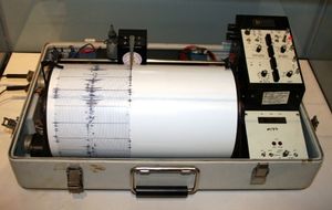
A seismograph, or seismometer, is an instrument used to detect and record earthquakes. Generally, it consists of a mass attached to a fixed base. During an earthquake, the base moves and the mass does not. The motion of the base with respect to the mass is commonly transformed into an electrical voltage. The electrical voltage is recorded on paper, magnetic tape, or another recording medium. This record is proportional to the motion of the seismometer mass relative to the Earth, but it can be mathematically converted to a record of the absolute motion of the ground.
Seismograph generally refers to the seismometer and its recording device as a single unit.
A seismometer is the internal part of the seismograph, which may be a pendulum or a mass mounted on a spring; however, it is often used synonymously with "seismograph".
Seismographs are installed in the ground throughout the world and operate as seismographic network.
A seismograph is securely mounted onto the surface of the Earth so that when the Earth shakes, the entire unit shakes with it, except for the mass on the spring which has inertia, and remains in the same place. As the seismograph shakes under (in the example below) the mass, the recording device on the mass records the realtive motion between itself and the rest of the instrument, thus recording the ground motion. In reality, these mechanisms are no longer manual, but instead work by measuring electronic changes produced by the motion of the ground with respect to the mass.
Seismograms are the records (paper copy) produced by seismographs used to calculate the location and magnitude of an earthquake. They show how the ground moves with the passage of time. On a seismogram, the horizontal axis = time (measured in seconds) and the vertical axis= ground displacement (usually measured in millimeters). When there is no earthquake reading there is just a straight line except for small wiggles caused by local disturbance or "noise" and the time markers. The movement of the seismometer in converted into a seismogram in one of several ways:
- a pen drawing an ink line on paper revolving on a drum
- a light beam making a trace on a moving photographic film
- electromagnetic system generating a current that is recorded electronically on tape
Contents
History
The first siesmograph was developed in 1890. The earliest "seismoscope" was invented by the Chinese philosopher Chang Heng in A.D. 132. The first "seismoscope" was a sculpture with carved dragons and frogs and balls that dropped from the dragon's mouth to a frog's mouth depending on where the earthquake occurred, or so they thought. This did not record earthquakes, however. It only indicated that there was one occurring.
Seismoscopes of limited effectiveness were used by Bina and others in the eighteenth century. The middle nineteenth century saw the invention by Palmieri of a seismoscope to record the times of small earthquakes.
A successful seismograph of low sensitivity was invented by Cecchi in 1875. British scientists at the College of Engineering, Tokyo, independently built seismographs in the 1880's. The British in Japan made many observations with their instruments and must be credited with first demonstrating the value to seismology of seismographic devices.
Von Rebeur-Paschwitz obtained the first recording of a teleseism in 1889. In the next decade, investigators in Italy, Germany, and England studied the waves from distant earthquakes and constructed the first teleseismic travel-time charts. Wiechert introduced a seismometer with viscous damping in 1898.
Theory seems to have been neglected in the early development of the seismograph. Theoretical studies of forced damped harmonic-oscillator seismographs were presented by Perry and Ayrton, and Lippmann, but these had little effect on the construction of seismographs. In the 1890's, the importance of tilt was much debated. By 1900, many seismologists had become convinced that the effect of tilting on seismograph response could usually be neglected.
Seismographs - Keeping Track of Earthquakes
Throw a rock into a pond or lake and watch the waves rippling out in all directions from the point of impact. Just as this impact sets waves in motion on a quiet pond, so an earthquake generates seismic waves that radiate out through the Earth.
Seismic waves lose much of their energy in traveling over great distances. But sensitive detectors (seismometers) can record theses waves emitted by even the smallest earthquakes. When these detectors are connected to a system that produces a permanent recording, they are called seismographs.
There are many different types seismometers, but they all are based on the fundamental principle - that the differential motion between a free mass (which tends to remain at rest) and a supporting structure anchored in the ground (which moves with the vibrating Earth) can be used to record seismic waves.

This principle is illustrated in figure. Vertical support AB holds mass M in position by wire AM and by strut BM at point B; the system becomes a seismometer when the vertical support is embedded in a concrete pier attached to the Earth. If there is no friction at the point B and mass M is reasonably large, the movement of the pier and the attached upright support in response to an earthquake wave will set up a differential motion between the mass and the pier (the inertia of the mass will make it remain at rest). This motion - the signal of an earthquake wave - can then be recorded on a revolving drum. When the pier is steady, the pen attached to the mass writes a straight line. But when the pier shakes, the mass and strut wiggle, recording waves from the earthquake that started the boom in motion.
Usually, the drum rotates on a screw-threaded axle so that the recording pen moves on a continuously advancing record and does not simply repeat the same circle over and over. Because time - both the time of day and the synchronization of events - is an important element in seismology, clocks are always part of a seismograph system.
A single seismograph pendulum works in only one direction, and cannot give a complete picture of wave motions from other directions. To overcome this problem, modern seismograph stations have three separate instruments to record horizontal waves - (1) one to record the north-south waves, (2) another to record east-west waves, and (3) a vertical one in which a weight resting on a spring tends to stand still and record vertical ground motions. The spring-suspended mass lags behind the motion caused by the earthquake, making the pen record the waves on the drum. This combination of instruments tells a seismologist the general direction of the seismic wave source, the magnitude at its source, and the character of the wave motion. Instruments at other stations must be used to get a precise fix on the earthquake's epicenter.
An earthquake generates a series of waves that penetrate the entire Earth and travel at and through its surface. Each wave has a characteristic time: each has its own move of travel. They are quite complex, but a few basic facts will explain how they travel through the Earth and how an earthquake's epicenter can be determined from seismograph records.
There are four basic types of seismic waves; two preliminary body waves that travel through the Earth and two that travel only at the surface (L waves). Combinations, reflections, and diffractions produce an infinity of other types, but body waves are the main interest in this discussion.
Body waves are composed of two principal types; the P (primary) wave, comparable to sound waves, which compresses and dilates the rock as it travels forward through the Earth; and the S (secondary) wave, which shakes the rock sideways as it advances at barely more than half the P-wave speed.
The P wave is designated the primary preliminary wave because it is the first to arrive at a seismic station after an earthquake. It travels at a speed usually less than 6 kilometers per second in the Earth's crust and jumps to 13 kilometers per second through the core.
The S wave is the secondary preliminary wave to be recorded. It follows paths through the Earth quite similar to those of the P-wave paths, except that no consistent evidence has yet been found that the S wave penetrates the Earth's core.
The lines labeled P, S, and L in the curves shown on figure 2 represent the travel time required for each phase at distances of 0 to 1300 kilometers from the earthquake's epicenter. They mark the points on the record at which these waves first arrive at the station.
The simplest method of locating an earthquake on a globe is to find the time interval between the P- and S-wave arrivals at several seismograph stations. The distance to the earthquake from each station is then determined from standard travel-time tables and travel-time curves. Great-circle arcs are drawn on the globe using the distance of the earthquake to the station as a radius. All the arcs should intersect at a common point - the epicenter.
Another method of locating an earthquake is to use the P-wave arrival-time minus origin-time (P - O) interval instead of distance. This method is more common because the time can be taken directly from surface focus travel-time tables assuming an origin of 00 hours. This method, however, requires that travel-time tables be available for various depths of focus. For locating a deep shock, one 700 kilometers deep, for example, travel-time tables and travel-time curves for that depth have to be used to calculate the origin time and distances.
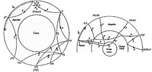
Other wave types can be generated inside the Earth by P and S waves, as shown in figure 3. As many as five different wave groups or phases can emerge when a P or S wave encounters a discontinuity or interface within the Earth.
This section of the article was abridged from Earthquake Information Bulletin. Vol. 2, No. 5, September - October, 1970.
Building Your Own Seismograph
It is relatively easy to acquire the necessary materials and build your own seismometer. The links here are to various sources with information on how to build a seismometer. They range from very simple and inexpensive to sophisticated and pricey.
- Build your own Seismograph Station - Redwood City, CA Public Seismic Network
- Build Your Own Seismograph -Univ. of CA, Berkeley
- PEPP Instruments -Indiana University PEPP Earthquake Institute Home Page
- GeoTool
- Amateur Seismologist
- Homebuilt Seismograph FAQ
Further Reading
The following links provide some more information about seismographs and earthquakes.
- Animation of P, S & Surface Waves
- Animations of Seismology Fundamentals
- Earth Science Education Activities
- Earthquake Monitoring
- Earthquakes
- Earthquakes by Bruce A. Bolt Online Companion
- Education & Outreach Software
- Global Earthquake Explorer
- John Lahr's Earthquake website
- McConnell, D., D. Steer, C. Knight, K. Owens, and L. Park. 2010. The Good Earth. 2nd Edition. McGraw-Hill, Dubuque, Iowa.
- Plummer, C., D. Carlson, and L. Hammersle. 2010. Physical Geology. 13th Edition. McGraw-Hill, Dubuque, Iowa.
- Quake-Catcher Network
- Science Explained
- Seismographs: Keeping Track of Earthquakes
- Tarbuck, E.J., F.K. Lutgens, and D. Tasa. 2009. Earth Science. 12th Edition. Prentice Hall, Upper Saddle River, New Jersey.
- Tracing earthquakes: seismology in the classroom
- UPSeis Seismology Questions Answered


