DRYIT Semi-Continuous Tray Drier
Practical Action
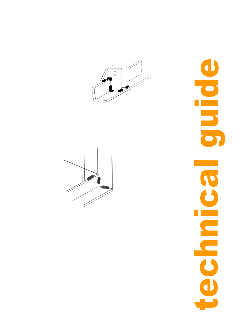
3) Cut out and drill the finger supports (see TD002) and then weld them to the two bottom
beams, as shown in figure 11. Minimise distortion by restraining the lower beam (with vice,
clamp etc) during welding and cooling and by keeping the weld material uiaed to a minimum.
Note that weld is not applied to the underside of the over hang. This area must be clear, for
positioning of the base joining pads.
No weld here
Figure 11: Finger supports
CORRECT POSITIONING OF THE SUPPORTS IS ESSENTIAL FOR CORRECT
FUNCTIONING OF THE LIFTING FINGERS. THE POSITIONING AND DIMNENSIONS OF
ALL MEMEMBERS ARE GIVEN IN TD 002.
4) Chamfer the ends of the lower beams to achieve a square, flush fit with the legs, as
shown in figure 12.
3mm chamfer
5) Weld two legs to each bottom
beam, ensuring they are square
Figure 12: Chamfered end to lower beam
Now assemble these with the
rectangle and add the centre beam,
centre supports, centre legs and
bearing block supports. Do not
weld on the top side of the bearing
supports as the bearing must sit
flat. Note: the cut-outs in the centre
beam are for the bearing shafts.
Take care to ensure the frame is
square and vertical before full
welding.
DO NOT drill any holes apart from those in the finger supports at this stage. The hole
positions shown in the drawing TD002 are theoretical and are actually located by marking
through holes in other assemblies, as described in General Assembly
13