Repeat the starting test (diagram 43) with each of the four rotor studs in the 3
o'clock position. Try different weights, and find the lightest weight which will
start the rotor turning. If one stud needs much more weight than another, then the
rotor is not balanced. Fix small weights to the rotor until the balance is correct.
Electrical testing
Coil connection test
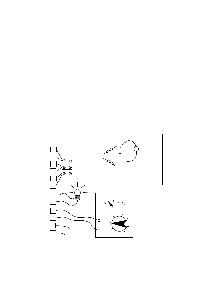
It would be helpful to have a multimeter when testing the PMG, but it is possible to
do some basic tests with a 3 volt torch bulb. See diagram 44.
• Connect the wires 1B to 4A, 2B to 5A, and 3B to 6A. (Series connections of pairs
of coils which are in the same phase.)
• Set the multimeter to '10VAC' or similar (if you have one).
• Connect the meter, or a bulb, between the wires marked 1A and 4B.
44. TESTING THE COILS
WIRING
DIAGRAM
CIRCUIT
SCHEMATIC
DIAGRAM
1B BLOCK
4A CONNECTOR
2B
SERIES
CONNECTIONS
5A
3B
6A
1A
4B BULB
BULB OR
METER
2A
5B
3A
6B TEST THESE
NEXT
ACV100
10
1
MULTIMETER
• Rotate the PMG slowly by hand, about one revolution per second.
• The meter should give a reading of about two volts, or the bulb should flicker.
• Repeat the test with two more pairs of wires: 2A and 5B, 3A and 6B.
In each case the result should be the same.
PMG manual
page 42
June 2001