• Cut a small flat steel plate 60 x 30 x 6 mm (suggested sizes) and fix it securely
or weld it to the end of the crankshaft as shown in diagram 6.
• Drill 2 holes, 6mm diameter and 40mm apart, centred on the shaft.
6. STEEL PLATE
60
30
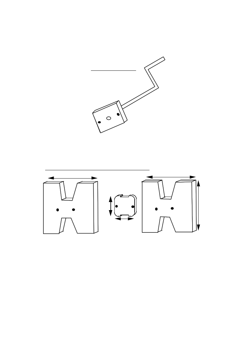
• Cut out 3 pieces of 13mm plywood as in diagram 7.
7. COIL-FORMER AND CHEEK PIECES
125 125
20 20
50
20
50
125
The coil former is 50mm by 50mm by 13 thick. It has rounded corners. The two
'cheek pieces' are 125mm by 125mm. There are 20mm wide notches top and bottom
in each. The notches are for putting masking tape under the coil, so that it can be
taped up before removing it from the former.
• Stack the pieces with the notches in line (diagram 8), and drill holes for the
mounting bolts.
The holes are 6mm diameter and 40mm apart.
Use a drill press to drill the holes exactly square to the plywood.
PMG manual
page 11
June 2001