Inductance
Mutual inductance refers to the effect Faraday's Law of induction has from one device on another, such as the energy a primary coil transmits to the secondary coil in a transformer.
Read this text, which explains how when we look at a coil as a circuit element, we can eliminate the magnetic field from Faraday's Law by using the fact that the magnetic field is always proportional to the current that created it in the first place. The result is that the emf across the coil is given by  . Here,
  is the change in the current during time
  , and
, and  is a proportionality constant called the inductance.
With the concept of inductance, we have turned coils into a circuit element by hiding all the details of the coil's geometry and magnetic properties in the single quantity , the inductance. This is analogous to how we turned capacitors into circuit elements by hiding their details in the capacitance (C). Knowing these characteristic constants is sufficient to calculate how inductors (our new name for coils) and capacitors behave in electrical circuits.
Inductors
Induction is the process in which an emf is induced by changing magnetic flux. Many examples have been discussed so far, some more effective than others. Transformers, for example, are designed to be particularly effective at inducing a desired voltage and current with very little loss of energy to other forms. Is there a useful physical quantity related to how “effective” a given device is? The answer is yes, and that physical quantity is called inductance.
Mutual inductance is the effect of Faraday’s law of induction for one device upon another, such as the primary coil in transmitting energy to the secondary in a transformer. See Figure 23.39, where simple coils induce emfs in one another.
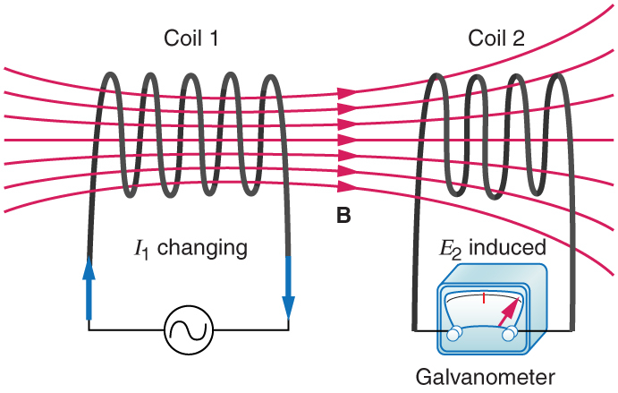
Figure 23.39 These coils can induce emfs in one another like an inefficient transformer. Their mutual inductance  indicates the effe ctiveness of the coupling between them. Here a change in current in coil 1 is seen to induce an emf in coil 2. (Note
that "
indicates the effe ctiveness of the coupling between them. Here a change in current in coil 1 is seen to induce an emf in coil 2. (Note
that " induced" represents the induced emf in coil 2.)
In the many cases where the geometry of the devices is fixed, flux is changed by varying current. We therefore concentrate on the rate of change of current,  , as the cause of induction. A change in the current
  in one device,
coil 1 in the figure, induces an
in one device,
coil 1 in the figure, induces an  in the other. We express this in equation form as
 [Equation 23.34]
where is defined to be the mutual inductance between the two devices. The minus sign is an expression of Lenz’s law. The larger the mutual inductance , the more effective the coupling. For example, the coils in Figure 23.39 have a small compared with the transformer coils in Figure 23.28. Units for are (/A=\Omega \cdot s") , which is named a henry (H), after Joseph Henry. That is,
, which is named a henry (H), after Joseph Henry. That is,  .
.
Nature is symmetric here. If we change the current  in coil 2, we induce an
  in coil 1, which is given by
 [Equation 23.35]
where is the same as for the reverse process. Transformers run backward with the same effectiveness, or mutual inductance .
A large mutual inductance may or may not be desirable. We want a transformer to have a large mutual inductance. But an appliance, such as an electric clothes dryer, can induce a dangerous emf on its case if the mutual inductance between its coils
and the case is large. One way to reduce mutual inductance is to counterwind coils to cancel the magnetic field produced. (See Figure 23.40.)
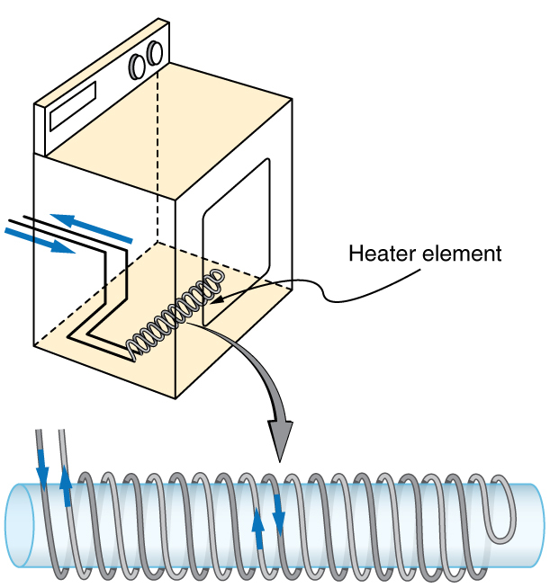
Figure 23.40 The heating coils of an electric clothes dryer can be counter-wound so that their magnetic fields cancel one another, greatly reducing the mutual inductance with the case of the dryer.
Self-inductance, the effect of Faraday’s law of induction of a device on itself, also exists. When, for example, current through a coil is increased, the magnetic field and flux also increase, inducing a counter emf, as required by Lenz’s law. Conversely,
if the current is decreased, an emf is induced that opposes the decrease. Most devices have a fixed geometry, and so the change in flux is due entirely to the change in current through the device. The induced emf is related to the
physical geometry of the device and the rate of change of current. It is given by
 [Equation 23.36]
where is the self-inductance of the device. A device that exhibits significant self-inductance is called an inductor, and given the symbol in Figure 23.41.
![]()
Figure 23.41
The minus sign is an expression of Lenz’s law, indicating that emf opposes the change in current. Units of self-inductance are henries (H) just as for mutual inductance. The larger the self-inductance of a device, the greater its opposition
to any change in current through it. For example, a large coil with many turns and an iron core has a large and will not allow current to change quickly. To avoid this effect, a small must be achieved, such as by counterwinding
coils as in Figure 23.40.
A 1 H inductor is a large inductor. To illustrate this, consider a device with  that has a 10 A current flowing through it. What happens if we try to shut off the current rapidly, perhaps in only 1.0 ms? An emf, given by
 ") , will oppose the change. Thus an emf will be induced given by
, will oppose the change. Thus an emf will be induced given by ![emf=-L(\Delta I/\Delta t)=(1.0\:H)[(10\:A)/(1.0\:ms)]=10,000\:V](../../filter/tex/pix.php/16c42ddd4823b3c586e9015f55ad973a.svg "emf=-L(\Delta I/\Delta t)=(1.0\:H)[(10\:A)/(1.0\:ms)]=10,000\:V") . The positive sign means this large voltage is in the same direction as the current, opposing its
decrease. Such large emfs can cause arcs, damaging switching equipment, and so it may be necessary to change current more slowly.
. The positive sign means this large voltage is in the same direction as the current, opposing its
decrease. Such large emfs can cause arcs, damaging switching equipment, and so it may be necessary to change current more slowly.
There are uses for such a large induced voltage. Camera flashes use a battery, two inductors that function as a transformer, and a switching system or oscillator to induce large voltages. (Remember that we need a changing magnetic field, brought about by a changing current, to induce a voltage in another coil.) The oscillator system will do this many times as the battery voltage is boosted to over one thousand volts. (You may hear the high pitched whine from the transformer as the capacitor is being charged.) A capacitor stores the high voltage for later use in powering the flash. (See Figure 23.42.)
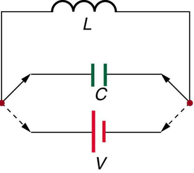
Figure 23.42 Through rapid switching of an inductor, 1.5 V batteries can be used to induce emfs of several thousand volts. This voltage can be used to store charge in a capacitor for later use, such as in a camera flash attachment.
It is possible to calculate for an inductor given its geometry (size and shape) and knowing the magnetic field that it produces. This is difficult in most cases, because of the complexity of the field created. So in this text the inductance
is usually a given quantity. One exception is the solenoid, because it has a very uniform field inside, a nearly zero field outside, and a simple shape. It is instructive to derive an equation for its inductance. We start by noting that
the induced emf is given by Faraday’s law of induction as ") } and, by the definition of self-inductance, as
} and, by the definition of self-inductance, as ") . Equating these yields
. Equating these yields
 [Equation 23.37]
Solving for gives
 [Equation 23.38]
This equation for the self-inductance of a device is always valid. It means that self-inductance depends on how effective the current is in creating flux; the more effective, the greater  is.
is.
Let us use this last equation to find an expression for the inductance of a solenoid. Since the area  of a solenoid is fixed, the change in flux is
 =A\Delta B") . To find
. To find  , we note that the magnetic
field of a solenoid is given by
, we note that the magnetic
field of a solenoid is given by  . (Here
  , where
  is the number of coils and
  is the solenoid’s length.) Only the current changes, so that
  . Substituting
  into gives
 [Equation 23.39]
This simplifies to
 (solenoid) [Equation 23.40]
This is the self-inductance of a solenoid of cross-sectional area and length . Note that the inductance depends only on the physical characteristics of the solenoid, consistent with its definition.
Example 23.7 Calculating the Self-inductance of a Moderate Size Solenoid
Calculate the self-inductance of a 10.0 cm long, 4.00 cm diameter solenoid that has 200 coils.
Strategy
This is a straightforward application of , since all quantities in the equation except are known.
Solution
Use the following expression for the self-inductance of a solenoid:
[Equation 23.41]
The cross-sectional area in this example is (0.0200\:m)^{2}=1.26\times 10^{-3}\:m^{2}") , is given to be 200, and the length is 0.100 m. We know the permeability of free space is
, is given to be 200, and the length is 0.100 m. We know the permeability of free space is  . Substituting these into the expression for gives
(200)^{2}(1.26\times 10^{-3}m^{2})}{0.100\:m}") [Equation 23.42]
[Equation 23.42]

Discussion
This solenoid is moderate in size. Its inductance of nearly a millihenry is also considered moderate.
One common application of inductance is used in traffic lights that can tell when vehicles are waiting at the intersection. An electrical circuit with an inductor is placed in the road under the place a waiting car will stop over. The body of the car increases the inductance and the circuit changes sending a signal to the traffic lights to change colors. Similarly, metal detectors used for airport security employ the same technique.
A coil or inductor in the metal detector frame acts as both a transmitter and a receiver. The pulsed signal in the transmitter coil induces a signal in the receiver. The self-inductance of the circuit is affected by any metal object in the path. Such detectors can be adjusted for sensitivity and also can indicate the approximate location of metal found on a person. (But they will not be able to detect any plastic explosive such as that found on the “underwear bomber.”) See Figure 23.43.

Figure 23.43 The familiar security gate at an airport can not only detect metals but also indicate their approximate height above the floor. (credit: Alexbuirds, Wikimedia Commons)
Energy Stored in an Inductor
We know from Lenz’s law that inductances oppose changes in current. There is an alternative way to look at this opposition that is based on energy. Energy is stored in a magnetic field. It takes time to build up energy, and it also takes
time to deplete energy; hence, there is an opposition to rapid change. In an inductor, the magnetic field is directly proportional to current and to the inductance of the device. It can be shown that the energy stored in an inductor  is given by
 [Equation 23.43]
This expression is similar to that for the energy stored in a capacitor.
Example 23.8 Calculating the Energy Stored in the Field of a Solenoid
How much energy is stored in the 0.632 mH inductor of the preceding example when a 30.0 A current flows through it?
Strategy
The energy is given by the equation , and all quantities except are known.
Solution
Substituting the value for found in the previous example and the given current into gives
[Equation 23.44]
(30.0\:A)^{2}=0.284\:J")
Discussion
This amount of energy is certainly enough to cause a spark if the current is suddenly switched off. It cannot be built up instantaneously unless the power input is infinite.
Source: Rice University, https://openstax.org/books/college-physics/pages/23-9-inductance
 This work is licensed under a Creative Commons Attribution 4.0 License.