 Print book
 Print this chapter
Process-Oriented Design
The goal of design is to map the requirements of the application to a hardware and software environment. The result of process-oriented analysis – data flow diagrams, data dictionary entities, and so on – is translated into detailed specifications for hardware and software. The main output of process-oriented design includes structure charts, physical databases, and program specifications.
In this chapter, you will learn about the concepts and terminologies for process-oriented design and the steps of process-oriented design, including transaction analysis, transform analysis, and structure charts, as well as physical database design, program packages, and program design. You will also learn about the strengths
and weaknesses of process-oriented design.
4. Process Design Activities
4.2. Transform Analysis
Rules for Transform Analysis
In transform analysis we identify the central transform and afferent and efferent flows, create a first-cut structure chart, refine the chart as needed at this high level, decompose the processes into functions, and refine again as needed. These rules are summarized as follows:
1. Identify the central transform
2. Produce a first-cut structure chart
3. Based on the design strategy, decompose the processes into their component activities
4. Complete the structure chart
5. Evaluate the structure chart and redesign as required.
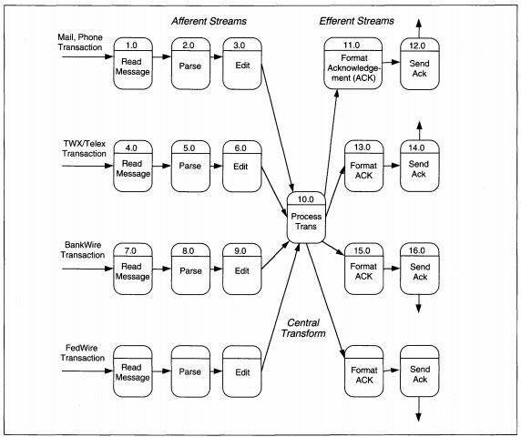
FIGURE 8-18 Detailed Money Transfer DFD Partitioned
To properly structure modules, their interrelationships and the nature of the application must be well understood. If a system concept has not yet been decided, design cannot be finalized until it is. The concept includes the timing of the application
as batch, on-line or real-time for each process, and a definition of how the modules will work together in production. This activity may be concurrent with transform analysis, but should have been decided to structure and package processes for an
efficient production environment. This activity is specific to the application and will be discussed again for ABC rental processing.
First, we identify the central transform and afferent and efferent flows. Look at the DFD and locate each stream of processing for each input. Trace each stream until you find the data flow that identifies valid, processable input that is the end of an
afferent stream. The afferent and efferent arcs refer only to the processes in the diagram. During this part of the transform analysis, files and data flows are ignored except in determining afferent and efferent flows. After identifying the afferent
flows, trace backward from specific outputs (files or flows to entities) to identify the efferent flows. The net afferent and efferent outputs are used to determine the initial structure of the structure chart, using a process called factoring.
Factoring is the act of placing each unbroken, single strand of processes into its own control structure, and of creating new control processes for split strands at the point of the split. The new control structure is placed under the input, process,
or output controls as appropriate.
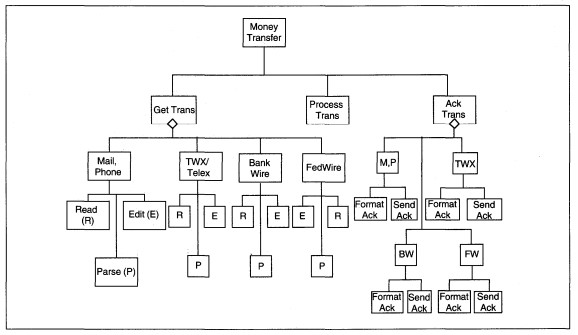
Figure 8-19 Sample Transaction Control Structure
| Transaction | General Process | Data |
|---|---|---|
| Add Customer | Maintenance | Customer |
| Change Customer | Maintenance | Customer |
| Delete Customer | Maintenance | Customer |
| Query Customer | Periodic | Customer |
| Add Video | Maintenance | Video |
| Change Video | Maintenance | Video |
| Delete Video | Maintenance | Video |
| Query Video |
Periodic | Video |
| Rent Video | Rent/Return | Video, Customer, History |
| Return Video | Rent/Return | Video, Customer, History |
| Assess special charges | Rent/Return | Customer |
| Query | Periodic | Video, Customer, History |
| Create History | Periodic | Video, Customer, History |
| Generate Reports | Periodic | Video, Customer, History |
TABLE 8-4 ABC Transaction List
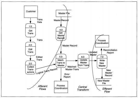
FIGURE 8-20 Master File Update DFD Partitioned
A master file update is shown as Figure 8-20 to trace the streams. In this diagram, we have two afferent data streams which come together at Match Trans to Master. The first input, Trans Data flows through process Get Trans and through Edit Trans to become
Edited Trans. Successfully edited transaction parts flow through Collect Transactions to become Logical Trans Record.
The second input stream deals with the master file. The Master Record is input to Get Master Record; successfully read master records flow through the process. Once the Logical Trans Record and Master Record are both present, the input transformations are complete. These two afferent streams completely describe inputs, and the arc is drawn over the Logical Trans Record and Master Record data flows (see Figure 8-20).
The two streams of data are first processed together in Match Trans to Master. Information to be updated flows through Update Master from Trans to become Updated Master. The error report coming from the match process is considered a trivial output and
does not change the essential transform nature of the process. The argument that Match Trans to Master is part of the afferent stream might be made. While it could be treated as such, the input data is ready to be processed; that is, transactions
by themselves, master records by themselves, and transactions with master records might all be processed. Here, we interpret the first transformation as matching.
The data flow out of Update Master from Trans is a net outflow, and Write New Master is an efferent process. The efferent arc is drawn over the data flow Updated Master.
Next, we factor three basic structures that relate to input-process-output processing (see Figure 8-21). If there is more than one process in a stream, getting the net output data may require some interprocess coordination. The coordination activities
are grouped and identified by a name that identifies the net output data. So, in the example, the input stream is Get Input; the transform stream is Process; the output stream is Write New Master. Each stream represents the major elements of
processing. Because the process and input streams both are compound, each has at least two streams beneath them-one for each sequential process stream to reach the net output data.
Notice that the DFD process names identify both data and transformation processes. Make sure that the lowest-level names on the structure chart are identical to the name on the data flow diagram to simplify completeness checking.
Notice also that there is transformation processing within the afferent and efferent streams. Modules frequently mix input/output and transform processing, and there is no absolute way to distinguish into which stream the module belongs. The rule
of thumb is to place a module in the stream which best describes the majority of its processing.
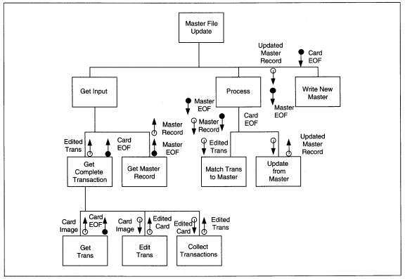
FIGURE 8-21 Master File Update Structure Diagram
Once the module is on the structure chart, we specifically evaluate it to ensure that it meets the principles of fan-out, span of control, maximal cohesion, and minimal coupling. If it violates even one principle, experiment with moving the module to the alternative streams and test if it better balances processing, without changing the processing. If so, leave it in the new location; otherwise note that the unbalanced part of the structure chart may need special design attention to avoid production bottlenecks.
Decompose the structure chart entries for each process. The three heuristics to guide the decomposition are:
- Is the decomposition also an IPO structure? If yes, continue; if no, do not decompose it.
- Does the control of the decomposed processing change? If yes, do not decompose it. If no, continue.
- Does the nature of the process change? That is, if the process is a date-validation, for instance, once it is decomposed is it still a date-validation? If no, continue. If yes, do not decompose it. In this example, I might try to decompose a date-validation into month-validate, day-validate, and year-validate. I would need to add a date-validate to check all three pieces together. Instead of a plain date-validate, I have ( a) changed the nature of the process, and (b) added control logic that was not necessary.
The thought process in analyzing depth is similar to that used in analyzing the number of organizational levels in reengineering. We want only those levels that are required to control hierarchic complexity. Any extra levels of hierarchy should be omitted.
Now let us turn to ABC rental processing to do transform analysis and develop the structure chart.
ABC Video Example Transform Analysis
The decisions about factoring are based on the principles of coupling and cohesion, but they also require a detailed understanding of the problem and a design approach that solves the whole problem. In ABC Video's case, we have to decide what the
relationships of rent, return, history, and maintenance processing are to each other. If you have not done this yet, now is the time to do it. Before we continue with design of transform analysis, then, we first discuss the design approach and rationale.
DESIGN APPROACH AND RATIONALE. In Chapter 7, Table 7-5 identified the Structured English pseudo-code for ABC's rental processing and we did not discuss it in detail. Now, we want to examine it carefully to determine an efficient, cohesive, and minimally
coupled decomposition of the process. When we partition the ABC Level 0 DFD from Figure 7-26, customer and video maintenance are afferent streams, reports are efferent, and rental and return are the central transform& (see Figure 8-22). We will
attend only to create and return rentals since they are the essence and hardest portion of the application.
There is a design decision to have return processing as a subprocess of rental processing that needs some discussion. Then we will continue with the design. The overall design could be to separate rentals and returns as two different processes, but are they? Think in the context of the video store about how the interactions with customers takes place. Customers return tapes previously taken out. Then they select tapes for rental and pay all outstanding fees, including current and past returns that generate late fees. To have late fees, a tape must have been returned. 2 Rentals and returns are separated in time; they have separate actions taken on files. ABC has any combination of rentals with returns (with or without late fees) and open rentals. All open rentals are viewed during rental processing, but need not be during return processing. Adding a return date and late fees is a trivial addition. Returns could be independent of rentals, so there are three design alternatives:
- Returns are separated from rentals.
- Rentals are a subset of returns.
- Returns are a subset of rentals.
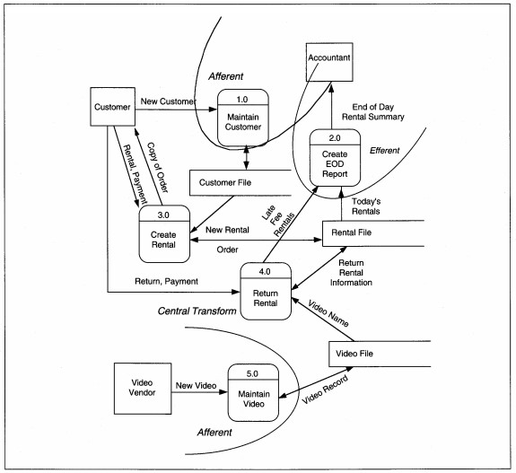
FIGURE 8-22 ABC Video Level 0 DFD Partitioned (same as Figure 7-26)
If returns are separated from rentals, there would be two payment processes-one for the return and one for the rental. If a rental includes a return, this is not 'minimal bureaucracy' and is not desirable. However, since returns can be done independently from rentals, the system should not require rental processing to do a return. This alternative is an acceptable partial solution, but the rest of the solution must be included.
The second alternative is to treat rentals as part of the return process. This reasoning recognizes that a rental precedes a return. All returns would need a rental/no rental indicator entry and assume that more than 50% of the time, rentals accompany
returns.
Which happens more frequently-returns with rentals, or rentals without returns? Let's say Vic does not know and reason through the process. Since returns can be any of three ways, only one of which is with rentals, coupling them as rental-within-return should be less efficient than either of the other two choices.
Last, we can treat returns as part of the rental process. If returns are within rentals, we have some different issues. What information identifies the beginning of a rental? What identifies the beginning of a return? A customer number could be used to
signify rental processing and a video number could signify a return. If we do this, we need to make sure the numbering schemes are distinct and nonoverlapping. We could have menu selection for both rental and return that determines the start of processing;
then return processing also could be called a subprocess of rentals. Either of these choices would work if we choose this option. For both alternatives, the software needs to be reevaluated to maximize reusable modules because many actions on rentals
are also taken on returns, including reading and display of open rentals and customer information.
Having identified the alternatives and issues, we conduct observations and collect data to justify a selection. The results show that 90% of returns, or about 180 tapes per day, are on time. Of those, 50% are returned through the drop box, and 50% (90 tapes) are returned in person with new rentals. The remaining 10% of returns also have about 50% (10 tapes) accompanying new rentals. So, about 100 tapes a day, or 50% of rentals are the return-then-rent type. These numbers justify having returns as a subprocess of rentals. They also justify having returns as a stand-alone process. We will allow both.
Deciding to support both separate and return-within-rental processing means that we must consciously decide on reusable modules for the activities the two functions both perform: reading and display of open rentals and customer information, payment processing,
and writing of processing results to the open rental files. We will try to design with at least these functions as reusable modules.
DEVELOP AND DECOMPOSE THE STRUCTURE CHART. To begin transform analysis, we start with the last DFD created in the analysis phase, and the data dictionary entries that define the DFD details. Figure 7-28 is reproduced here as Figure 8-23, with a first-cut partitioning to identify the central transform. First, we evaluate each process. We will use the pseudo-code that is in the data dictionary (see Figure 8-24). The DFD shows three rental subprocesses: Get Valid Rental, Process Fees and Money, and Create and Print Rental. Each of the subprocesses might be further divided into logical components. Try to split a routine into a subroutine for each function or data change.
First, evaluate the potential split to make sure the subroutines are all still needed to do the routine. This double-checks that the original thinking was correct. Then, evaluate each potential split asking if adding the subroutine changes the control,
nature, or processing of the routine. If yes, do not separate the routine from the rest of the logic; if no, abstract out the subroutine.
For ABC, Get Valid Rental is the most complex of the routines and is evaluated in detail. Get Valid Rental has three subroutines that we evaluate: Get Valid Customer, Get Open Rentals, and Get Valid Video. These splits are based on the different files that are read to obtain data for processing a rental. Without all three of these actions, we do not have a valid rental, so the original designation of Get Valid Rental appears correct. Figure 8-25 shows refined pseudo-code for ABC rental processing with clearer structure and only structured constructs. Subroutines are shown with their own headings.
If we are to accommodate returns during rental processing, we have to decide where and how rentals fit into the pseudo-code. We want to allow return dates to be added to open rentals. We also want to allow returns before rentals and returns within rentals.
This implies that there are two places in the process where a rental Video ID might be entered: before or after the Customer ID. If the Video ID is entered first, the application would initiate in the Return process; from there, we need to allow additional
rentals. If the Customer ID is entered first, the application would initiate rental; from there, we need to allow returns. To allow both of these actions to lead to rental and/or return processing, we need to add some control structure to the pseudo-code
(see Figure 8-26). The control structure also changes the resulting structure chart somewhat even though the DFDs are not changed.
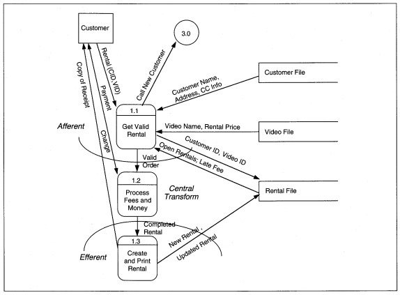
FIGURE 8-23 ABC Video Level l DFD Partitioned (same as Figure 7-28)
Next, we evaluate the refined pseudo-code and inspect each subroutine individually to determine if further decomposition is feasible (see Figure 8-27). For Get Valid Customer, does the processing stay the same? That is, are the detail lines of procedure information the same? By adding the subroutine we want to add a level of abstraction but not new logic. In this case, the answer is yes. Now look at the details of Get Valid Customer. The subprocesses are Get Customer Number-a screen input process, Read and Test Customer File-a disk input process with logic to test read success and determine credit worthiness, and Display Customer Info-a screen output process. Again, we have decomposed Get Valid Customer without changing the logic or adding any new functions.
The results of the other evaluations are presented. Walk-through the same procedure and see if you develop the same subroutines. Here we used the pseudo-code to decompose, but we could have used text or only our knowledge of processing to describe this
thinking. When the decomposition is complete for a particular process stream, it is translated to a structure chart.