Ethernet
Read this section. MAC addresses are the datalink services found in an Ethernet environment.
6.3.2 Ethernet
Ethernet was designed in the 1970s at the Palo Alto Research Center [Metcalfe1976]. The first prototype 4 used a coaxial cable as the shared medium and 3 Mbps of bandwidth. Ethernet was improved during the late 1970s and in the 1980s, Digital Equipment, Intel and Xerox published the first official Ethernet specification [DIX]. This specification defines several important parameters for Ethernet networks. The first decision was to standardise the commercial Ethernet at 10 Mbps. The second decision was the duration of the slot time. In Ethernet, a long slot time enables networks to span a long distance but forces the host to use a larger minimum frame size. The compromise was a slot time of 51.2 microseconds, which corresponds to a minimum frame size of 64 bytes.
The third decision was the frame format. The experimental 3 Mbps Ethernet network built at Xerox used short frames containing 8 bit source and destination addresses fields, a 16 bit type indication, up to 554 bytes of payload and a 16 bit CRC. Using 8 bit addresses was suitable for an experimental network, but it was clearly too small for commercial deployments. Although the initial Ethernet specification [DIX] only allowed up to 1024 hosts on an Ethernet network, it also recommended three important changes compared to the networking technologies that were available at that time. The first change was to require each host attached to an Ethernet network to have a globally unique datalink layer address. Until then, datalink layer addresses were manually configured on each host. [DP1981] went against that state of the art and noted “Suitable installation-specific administrative procedures are also needed for assigning numbers to hosts on a network. If a host is moved from one network to another it may be necessary to change its host number if its former number is in use on the new network. This is easier said than done, as each network must have an administrator who must record the continuously changing state of the system (often on a piece of paper tacked to the wall !). It is anticipated that in future office environments, hosts locations will change as often as telephones are changed in present-day offices.” The second change introduced by Ethernet was to encode each address as a 48 bits field [DP1981]. 48 bit addresses were huge compared to the networking technologies available in the 1980s, but the huge address space had several advantages [DP1981] including the ability to allocate large blocks of addresses to manufacturers. Eventually, other LAN technologies opted for 48 bits addresses as well [802]_. The third change introduced by Ethernet was the definition of broadcast and multicast addresses. The need for multicast Ethernet was foreseen in [DP1981] and thanks to the size of the addressing space it was possible to reserve a large block of multicast addresses for each manufacturer.
The datalink layer addresses used in Ethernet networks are often called MAC addresses. They are structured as shown in the figure below. The first bit of the address indicates whether the address identifies a network adapter or a multicast group. The upper 24 bits are used to encode an Organisation Unique Identifier (OUI). This OUI identifies a block of addresses that has been allocated by the secretariat 5 who is responsible for the uniqueness of Ethernet addresses to a manufacturer. Once a manufacturer has received an OUI, it can build and sell products with one of the 16 million addresses in this block.
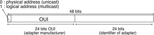
Figure 6.18: 48 bits Ethernet address format
The original 10 Mbps Ethernet specification [DIX] defined a simple frame format where each frame is composed of five fields. The Ethernet frame starts with a preamble (not shown in the figure below) that is used by the physical layer of the receiver to synchronise its clock with the sender’s clock. The first field of the frame is the destination address. As this address is placed at the beginning of the frame, an Ethernet interface can quickly verify whether it is the frame recipient and if not, cancel the processing of the arriving frame. The second field is the source address. While the destination address can be either a unicast or a multicast/broadcast address, the source address must always be a unicast address. The third field is a 16 bits integer that indicates which type of network layer packet is carried inside the frame. This field is often called the EtherType. Frequently used EtherType values 6 include 0x0800 for IPv4, 0x86DD for IPv6 and 0x806 for the Address Resolution Protocol (ARP).
The fourth part of the Ethernet frame is the payload. The minimum length of the payload is 46 bytes to ensure a minimum frame size, including the header of 512 bits. The Ethernet payload cannot be longer than 1500 bytes. This size was found reasonable when the first Ethernet specification was written. At that time, Xerox had been using its experimental 3 Mbps Ethernet that offered 554 bytes of payload and RFC 1122 required a minimum MTU of 572 bytes for IPv4. 1500 bytes was large enough to support these needs without forcing the network adapters to contain overly large memories. Furthermore, simulations and measurement studies performed in Ethernet networks revealed that CSMA/CD was able to achieve a very high utilization. This is illustrated in the figure below based on [SH1980], which shows the channel utilization achieved in Ethernet networks containing different numbers of hosts that are sending frames of different sizes.
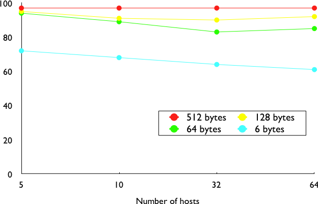
Figure 6.19: Impact of the frame length on the maximum channel utilisation [SH1980]
The last field of the Ethernet frame is a 32 bit Cyclical Redundancy Check (CRC). This CRC is able to catch a much larger number of transmission errors than the Internet checksum used by IP, UDP and TCP [SGP98]. The format of the Ethernet frame is shown below.
Note: Where should the CRC be located in a frame ?
The transport and datalink layers usually chose different strategies to place their CRCs or checksums. Transport layer protocols usually place their CRCs or checksums in the segment header. Datalink layer protocols sometimes place their CRC in the frame header, but often in a trailer at the end of the frame. This choice reflects implementa- tion assumptions, but also influences performance RFC 893. When the CRC is placed in the trailer, as in Ethernet, the datalink layer can compute it while transmitting the frame and insert it at the end of the transmission. All Eth- ernet interfaces use this optimisation today. When the checksum is placed in the header, as in a TCP segment, it is impossible for the network interface to compute it while transmitting the segment. Some network interfaces provide hardware assistance to compute the TCP checksum, but this is more complex than if the TCP checksum were placed in the trailer 8.

Figure 6.20: Ethernet DIX frame format
The Ethernet frame format shown above is specified in [DIX]. This is the format used to send both IPv4 RFC 894 and IPv6 packets RFC 2464. After the publication of [DIX], the Institute of Electrical and Electronic Engineers (IEEE) began to standardise several Local Area Network technologies. IEEE worked on several LAN technolo- gies, starting with Ethernet, Token Ring and Token Bus. These three technologies were completely different, but they all agreed to use the 48 bits MAC addresses specified initially for Ethernet [802]_. While developing its Ethernet standard [802.3], the IEEE 802.3 working group was confronted with a problem. Ethernet mandated a minimum payload size of 46 bytes, while some companies were looking for a LAN technology that could trans- parently transport short frames containing only a few bytes of payload. Such a frame can be sent by an Ethernet host by padding it to ensure that the payload is at least 46 bytes long. However since the Ethernet header [DIX] does not contain a length field, it is impossible for the receiver to determine how many useful bytes were placed inside the payload field. To solve this problem, the IEEE decided to replace the Type field of the Ethernet [DIX] header with a length field 9. This Length field contains the number of useful bytes in the frame payload. The pay- load must still contain at least 46 bytes, but padding bytes are added by the sender and removed by the receiver. In order to add the Length field without significantly changing the frame format, IEEE had to remove the Type field. Without this field, it is impossible for a receiving host to identify the type of network layer packet inside a received frame. To solve this new problem, IEEE developed a completely new sublayer called the Logical Link Control [802.2]. Several protocols were defined in this sublayer. One of them provided a slightly different version of the Type field of the original Ethernet frame format. Another contained acknowledgements and retransmissions to provide a reliable service... In practice, [802.2] is never used to support IP in Ethernet networks. The figure below shows the official [802.3] frame format.

Figure 6.21: Ethernet 802.3 frame format
Note: What is the Ethernet service ?
An Ethernet network provides an unreliable connectionless service. It supports three different transmission modes [unicast, multicast and broadcast. While the Ethernet service is unreliable in theory, a good Ethernet network should, in practice, provide a service that:]
- delivers frames to their destination with a very high probability of successful delivery
- does not reorder the transmitted frames
The first property is a consequence of the utilisation of CSMA/CD. The second property is a consequence of the physical organisation of the Ethernet network as a shared bus. These two properties are important and all evolutions of the Ethernet technology have preserved them.
Several physical layers have been defined for Ethernet networks. The first physical layer, usually called 10Base5, provided 10 Mbps over a thick coaxial cable. The characteristics of the cable and the transceivers that were used then enabled the utilisation of 500 meter long segments. A 10Base5 network can also include repeaters between segments.
The second physical layer was 10Base2. This physical layer used a thin coaxial cable that was easier to install than the 10Base5 cable, but could not be longer than 185 meters. A 10BaseF physical layer was also defined to transport Ethernet over point-to-point optical links. The major change to the physical layer was the support of twisted pairs in the 10BaseT specification. Twisted pair cables are traditionally used to support the telephone service in office buildings. Most office buildings today are equipped with structured cabling. Several twisted pair cables are installed between any room and a central telecom closet per building or per floor in large buildings. These telecom closets act as concentration points for the telephone service but also for LANs.
The introduction of the twisted pairs led to two major changes to Ethernet. The first change concerns the physical topology of the network. 10Base2 and 10Base5 networks are shared buses, the coaxial cable typically passes through each room that contains a connected computer. A 10BaseT network is a star-shaped network. All the devices connected to the network are attached to a twisted pair cable that ends in the telecom closet. From a maintenance perspective, this is a major improvement. The cable is a weak point in 10Base2 and 10Base5 networks. Any physical damage on the cable broke the entire network and when such a failure occurred, the network administrator had to manually check the entire cable to detect where it was damaged. With 10BaseT, when one twisted pair is damaged, only the device connected to this twisted pair is affected and this does not affect the other devices. The second major change introduced by 10BaseT was that is was impossible to build a 10BaseT network by simply connecting all the twisted pairs together. All the twisted pairs must be connected to a relay that operates in the physical layer. This relay is called an Ethernet hub. A hub is thus a physical layer relay that receives an electrical signal on one of its interfaces, regenerates the signal and transmits it over all its other interfaces. Some hubs are also able to convert the electrical signal from one physical layer to another (e.g. 10BaseT to 10Base2 conversion).
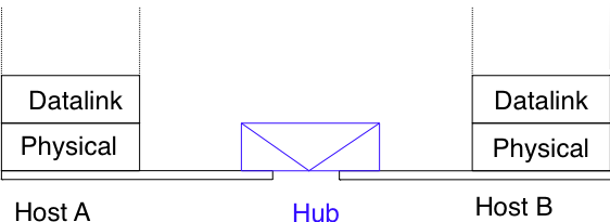
Figure 6.22: Ethernet hubs in the reference model
Computers can directly be attached to Ethernet hubs. Ethernet hubs themselves can be attached to other Ethernet hubs to build a larger network. However, some important guidelines must be followed when building a complex network with hubs. First, the network topology must be a tree. As hubs are relays in the physical layer, adding a link between Hub2 and Hub3 in the network below would create an electrical shortcut that would completely disrupt the network. This implies that there cannot be any redundancy in a hub-based network. A failure of a hub or of a link between two hubs would partition the network into two isolated networks. Second, as hubs are relays in the physical layer, collisions can happen and must be handled by CSMA/CD as in a 10Base5 network. This implies that the maximum delay between any pair of devices in the network cannot be longer than the 51.2 microseconds slot time. If the delay is longer, collisions between short frames may not be correctly detected. This constraint limits the geographical spread of 10BaseT networks containing hubs.
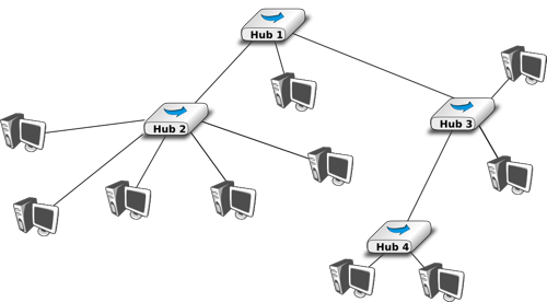
Figure 6.23: A hierarchical Ethernet network composed of hubs
In the late 1980s, 10 Mbps became too slow for some applications and network manufacturers developed several LAN technologies that offered higher bandwidth, such as the 100 Mbps FDDI LAN that used optical fibers. As the development of 10Base5, 10Base2 and 10BaseT had shown that Ethernet could be adapted to different physical layers, several manufacturers started to work on 100 Mbps Ethernet and convinced IEEE to standardise this new technology that was initially called Fast Ethernet. Fast Ethernet was designed under two constraints. First, Fast Ethernet had to support twisted pairs. Although it was easier from a physical layer perspective to support higher bandwidth on coaxial cables than on twisted pairs, coaxial cables were a nightmare from deployment and maintenance perspectives. Second, Fast Ethernet had to be perfectly compatible with the existing 10 Mbps Ethernets to allow Fast Ethernet technology to be used initially as a backbone technology to interconnect 10 Mbps Ethernet networks. This forced Fast Ethernet to use exactly the same frame format as 10 Mbps Ethernet. This implied that the minimum Fast Ethernet frame size remained at 512 bits. To preserve CSMA/CD with this minimum frame size and 100 Mbps instead of 10 Mbps, the duration of the slot time was decreased to 5.12 microseconds.
The evolution of Ethernet did not stop. In 1998, the IEEE published a first standard to provide Gigabit Ethernet over optical fibers. Several other types of physical layers were added afterwards. The 10 Gigabit Ethernet standard appeared in 2002. Work is ongoing to develop standards for 40 Gigabit and 100 Gigabit Ethernet and some are thinking about Terabit Ethernet. The table below lists the main Ethernet standards. A more detailed list may be found at http://en.wikipedia.org/wiki/Ethernet_physical_layer
|
Standard |
Comments |
10Base5 |
Thick coaxial cable, 500m |
Source: Olivier Bonaventure, https://s3.amazonaws.com/saylordotorg-resources/wwwresources/site/wp-content/uploads/2012/02/Computer-Networking-Principles-Bonaventure-1-30-31-OTC1.pdf This work is licensed under a Creative Commons Attribution 3.0 License.