 Print this chapter
UML Sequence Diagrams
9. A System Sequence Diagram
During requirements analysis phase, we define the system by treating it as a single black box so that the behaviour is a description of what a system does, without explaining how it does it. In this way, only system operations that an actor requests of the system will be considered. The interest is to find input events by making use of use cases and their scenario.
For example, the typical course of events in the Make Phone Calls indicates that the caller and callee generate the system input events that can be denoted as liftReceiver, dialPhoneNumber, answersPhone, hangsUp. In general, an event takes parameters.
UML Trace diagram is very useful in identifying the system operations, as in Figure 3.13 which show, for a particular course of events within a use case, the external actors that interact directly with the system, the system (as a black box), and the system input events that the actors generate. A simplified trace diagram which shows only system input events is called a system sequence diagram. A system sequence diagram (SSD) for the Make Phone Calls use case can be illustrated as in Figure 3.14.
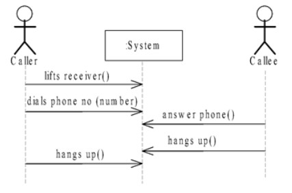
Figure 3.14: A System Sequence Diagram for the Make Phone Calls of a Telephone System