 Print book
UML Sequence Diagrams
| Site: | Saylor Academy |
| Course: | CS302: Software Engineering |
| Book: | UML Sequence Diagrams |
| Printed by: | Guest user |
| Date: | Friday, February 4, 2022, 6:12 PM |
Description
During the requirements analysis phase, the system can be treated as a single "black box", which means that we can look at the system's behavior (what it does) without explaining how it does it. Read this section to see an example of a simplified trace diagram that shows only system input events. This is called a system sequence diagram.
Table of contents
- 1. Introduction
- 2. Concepts and Classes in Conceptual Modelling
- 3. Identifying Concepts
- 4. Adding Associations in a Conceptual Model
- 5. Steps to Create a Conceptual Model
- 6. Conclusion
- 7. System Behaviour: System Sequence Diagrams and Operations
- 8. System Input Events and System Operations
- 9. A System Sequence Diagram
- 10. Recording system operations
- 11. System Operations Contracts
- 12. Documenting Contracts
- 13. Contracts for Some Operations in POST system
- 14. How to Create a Contract
- 15. Conclusion
1. Introduction
A central distinction between OOA and structured analysis is decomposition by concepts (objects) rather than decomposition by functions. The key point in this decomposition is to find what can behave, and then to decide later on in the design and implementation how they behave to realize the system functionality. Object-oriented requirement analysis is more concerned in identifying concepts related to the requirements and to create a conceptual model of the problem domain or the application area we are working with. This activity is will guide you on how to identifying objects or concepts and make them relate to each other and finally create a conceptual or domain diagram.
Source: Ellen Ambakisye Kalinga, https://oer.avu.org/bitstream/handle/123456789/667/CSI%203104_EN%20Object%20Oriented%20Analysis%20and%20Design1.pdf?sequence=1&isAllowed=y
 This work is licensed under a Creative Commons Attribution-ShareAlike 4.0 License.
2. Concepts and Classes in Conceptual Modelling
Conceptual Modelling (sometimes called Domain Modelling) is the activity of finding out which concepts are important to system. This process helps us to understand the problem further, and develop a better awareness of our customer's business. A concept is an idea, thing, or object. More formally, a concept may be considered in terms of its symbol, intension, and extension:
- Symbol – words or images representing a concept. It can be referred to when we talk about the concept.
- Intension – the definition of a concept.
- Extension – the set of examples or instances to which the concept applies.
- The intension to "represent a course offered as part of a degree in that university"; and
- The extension of all other modules offered by that university.
Note that the terms class and type are used more by UML and not concept. As long as we are in requirement analysis stage, the two terms class and concept may be used interchangeably.. Each instance of a class is called an object of the class. For example a class called "Student". JahnSmith and JaneBrown are instances of a class Student. Therefore, a class defines a set of objects.
The notions of class and object are interlinked as one cannot exist without the other, and any object belongs to a class. The differences are:
- An object is a concrete entity – exists in space and time (persistence property of objects);
- A class is an abstraction of a set of objects
3. Identifying Concepts
The requirement document which is up to now including: the overview, goal, functional requirements, use cases, use case diagram and use case descriptions is the good source of information in identifying concepts. Two activities that are fundamental to the useful application of object oriented in OOA are:
- To identify as many candidate objects from the problem domain, and
- Later select those candidate objects that are significant to develop and be specified in an object model (conceptual model)
Liu suggests the following candidate concepts from the requirement document as shown in Table 3.10.
Table 3.10: Guide to Identify Concepts
| Concept Category | Examples |
| physical or tangible objects (or things | POST (i.e. Point-of-Sale Unit), House, Car, Sheep, People, Airplane |
| places | Store, Office, Airport, Police Station |
| documents, specifications, designs, or descriptions of things | Product Specification, Module Description, Flight Description |
| transactions | Sale, Payment, Reservation |
| roles of people | Cashier, Student, Doctor, Pilot |
| containers of other things | Store, Bin, Library, Airplane |
| things in a container | Item, Book, Passenger |
| other computers or electromechanical systems external to our system | Credit Card Authorization System, Air-Traffic Control |
| abstract noun concepts | Hunger, Acrophobia |
| organizations | Sales Department, Club, Object Airline |
| historic events, incidents | Sale, Robbery, Meeting, Flight, Crash, Landing |
| Processes (often not represented as a concept, but may be) | Selling A Product, Booking A Seat |
| rules and policies | Refund Policy, Cancellation Policy |
| Catalogs | Product Catalog, Parts Catalog |
| records of finance, work, contracts, legal matters | Receipt, Ledger, Employment Contract, Maintenance Log |
| financial instruments and services | Line Of Credit, Stock |
| manuals, books | Employee Manual, Repair Manual |
Another useful and simple technique for the identification of concepts is to identify or extract noun and noun phrases from the requirement document and consider them as candidate concepts or attributes.
Warning:
Care must be applied when these methods are used; mechanical noun-to-concept mapping is not possible, words in natural languages are ambiguous, and concept categories may include concepts which are about either attributes, events or operations which should
not be modeled as classes. We should concentrate on the objects/classes involved in the realization of the use cases.
Consider the POST system, from the use case Buy Items with Cash. We can identify some noun phrases as shown in Figure 3.8. Some of the noun phrases in the use case are candidate concepts; some may be attributes of concepts.
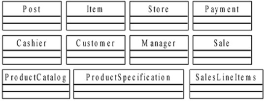
Figure 3.8: Selected Possible Concepts for the POST System
The following guidelines are useful when identifying concepts:
- It is better to over specify a conceptual model with lots of fine-grained concepts, than to under specify it.
- Do not exclude a concept simply because the requirements do not indicate an obvious need to remember information about it.
- It is common to miss concepts during the initial identification phase, and to discover them later during the consideration of attributes or associations, or during the design phase. When found, they are added to the conceptual model.
- Put a concept down as a candidate in the conceptual model when you are not sure it must not be included.
4. Adding Associations in a Conceptual Model
A conceptual model with totally independent concepts only is obviously useless, as objects in different classes must be related to each other so that they can interact and collaborate with each other to carry out processes. In UML, an association is a relationship between two classes that specifies how instances of the classes can be linked together to work together.
In the same sense that instances of a class are objects, instances of an association are links between objects of the two classes – this is what we meant that objects in the same class "share the same relationships".
With respect to an association between classes, an important information is about how many objects of one class (say "A") can be associated with one object of another (say "B")n , at a particular moment in time. We use multiplicity to represent this information. An example in Figure 3.9 shows the multiplicity expressions and their meanings.
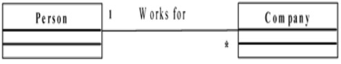
Figure 3.9: An Example on Multiplicity Use
Some high priority associations useful to include in a conceptual model are:
- A is a physical or logical part of B.
- A is physically or logically contained in/on B.
- A is recorded in B.
From the list of concepts identified, one can start thinking on the possible associations concepts have to each other. This can accelerate the creation of a conceptual diagram. In this way relevant associations will not be forgotten. Figure 3.10 shows possible aggregation relationships of concepts in a POST system.
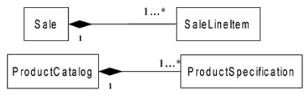
Figure 3.10: Aggregation Association in POST Application as an example, a conceptual model, or sometimes known as a class diagram for a POST system domain is as shown in Figure 3.11. This has also considered concepts' association: inheritance, aggregation and composition as discussed earlier.
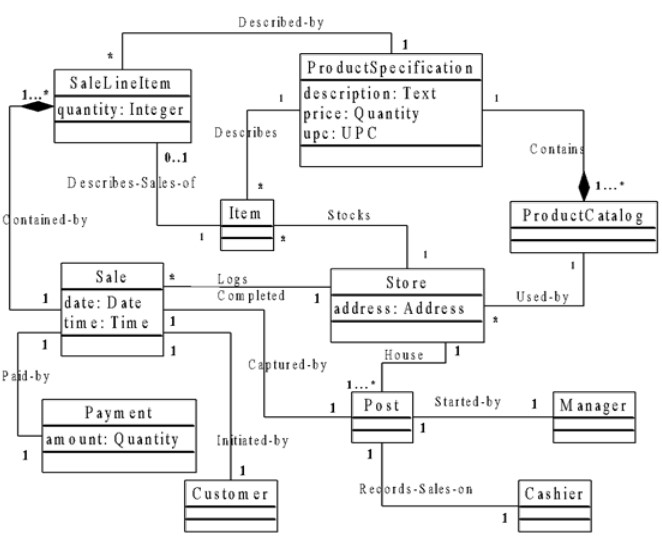
Figure. 3.11: A Conceptual/Class model for the POST System (concepts, associations and Attributes)
Add Attributes in a Conceptual Model Instances of a concept may have some properties. For examples, a Sale can have a date and time; a Payment can have amount, a Furniture can have a size, a Module can have a code, title, and number of credits, a Student has a name, registration number and age, etc.
An attribute of a class is the abstraction of a single characteristic or a property of entities that have been abstracted as objects of the class. At any given moment of time, the attribute of an individual object in the class is a logical data value representing the corresponding property of the object, and called the value of attribute for the object at that time. One object has exactly one value for each attribute at any given time. Therefore, the value for an attribute of an object may change over time. For examples,
- time and date are attributes of class Sale, and an instance of Sale can be a sale at 13.30 on 1/10/1998.
- code, title, and credit are three attributes of class Module, and an instance of Module can have a code MC 206, title: Software Engineering and System Development, and credit: 20.
- name and age are attributes of Student, an individual student can have the name John Smith, and age 19.
Something to note in attributes:
(a) The attributes in a conceptual model should be simple and clear without ambiguity. Examples of simple attributes are Date, Number, PhoneNumber, Name, Description, Code, Title etc
(b) In object-oriented approach no foreign keys. Attributes are not be used to relate concepts in the conceptual model, but to store some information about the objects themselves. Liu, (2001) state that the most common violation of this principle is to add a kind of foreign key attribute, as is typically done in relational database designs, in order to associate two types. For example, the currentPOSTNumber attribute in the Cashier type in Figure 3.12 is undesirable because its purpose is to relate the Cashier to a POST object. The better way to express that a Cashier uses a POST is with an association, not with a foreign key attribute Once again
Relate types with an association, not with an attribute
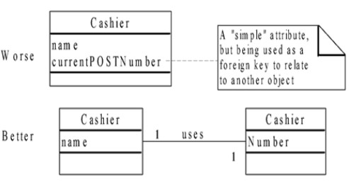
Figure 3.12: Do not use attributes as foreign keys
5. Steps to Create a Conceptual Model
The following steps can be applied to create a conceptual model:
- Identify and List candidate concepts using the Concept Category List and noun phrase identification related to the current requirements under consideration.
- Represent them in a conceptual model.
- Add associations necessary to record relationships for which there are a need to preserve some memory.
- Add the attributes necessary to fulfill the information requirements.
6. Conclusion
System concepts can be identified by investigating the requirement document which includes: system function, use cases and other initial reports on the domain. A conceptual model show the static view of associations of concepts, they include as shown in Figure: 3.8 above; Concepts, Relationship or association between concepts and Attributes of concepts. The following elements are not suitable in a conceptual model:
- A software artifact, such as a window or a database, unless the domain being modeled is of software concepts, such as a model of a graphical user interface.
- Operations (responsibilities) or methods.
7. System Behaviour: System Sequence Diagrams and Operations
Introduction
We need to identify the operations that the system needs to perform and in what order the system need to perform these operations to carry out a use case, and the effect of such an operation on the system, i.e. on the objects of the systems.
A use case defines a class of conversations between the actors and the system, and an individual conversation of this class is a realization of the use case. Obviously, there may be many realizations for a use case. A scenario of a use case is a particular instance or realized path through the use case, i.e. a particular realization of the use case.
This activity is intending to introduce system sequence diagrams which are used to find system events and system operations. Latter we will see how to create a contract of system operations.
System operations are the operations that system needs to perform to carry out a use case and the effects of these operations on the system. In this case, use cases – use case diagram and use case descriptions are inputs of this activity.
8. System Input Events and System Operations
When an actor interacts with the system for a certain use case, events are being generated to a system. This event is requesting the system to perform some operations in response. Liu, indicate that events generated by actors are very tightly related to operations that the system can perform. This implies that we identify system's operations by identifying events that actors generate.
By definition: A system input event is an external input generated by an actor to a system. A system input event initiates a responding operation while a system operation is an operation that the system executes in response to a system input event.
Some system operations also generate output events to the actors to prompt the next system event that an actor can perform; and A system event is either an input event or an output event.
Therefore, a system input event triggers a system operation, and a system operation response to a system input event.
As an example given by Liu, we can formally define a scenario of a use case as a sequence of system events that occur during a realization of the use case. Consider the use case of Make Phone Calls for a telephone system, which involves two actors, Caller (initiator) and Callee. The following sequence of events is a scenario of this use case:
| Input Events | Output Events |
| 1. Caller lifts a receiver | 2. Telephone starts dial tone |
| 3. Caller dials a number | 4. Telephone rings to Callee |
| 5. Telephone is ringing tone to Caller | |
| 6. Callee answers the ringing phone | 7. Telephone ringing tone stops |
| 8. Telephone ringing tone stops | |
| R9. Telephones connectedW6 | |
| 10. Callee hangs up by returning the telephone receiver | 11. connection broken |
| 12. Caller hangs up by returning the telephone receiver |
We can represent the set sequence of events is a scenario using event tracer diagram as shown in Figure 3.13:
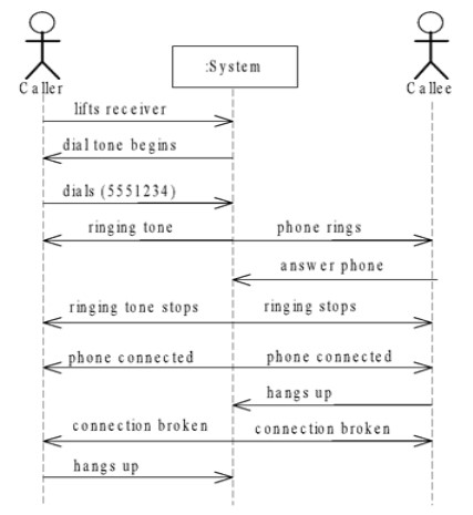
Figure 3.13: Telephone system event trace diagram for the "Make Phone Calls"
9. A System Sequence Diagram
During requirements analysis phase, we define the system by treating it as a single black box so that the behaviour is a description of what a system does, without explaining how it does it. In this way, only system operations that an actor requests of the system will be considered. The interest is to find input events by making use of use cases and their scenario.
For example, the typical course of events in the Make Phone Calls indicates that the caller and callee generate the system input events that can be denoted as liftReceiver, dialPhoneNumber, answersPhone, hangsUp. In general, an event takes parameters.
UML Trace diagram is very useful in identifying the system operations, as in Figure 3.13 which show, for a particular course of events within a use case, the external actors that interact directly with the system, the system (as a black box), and the system input events that the actors generate. A simplified trace diagram which shows only system input events is called a system sequence diagram. A system sequence diagram (SSD) for the Make Phone Calls use case can be illustrated as in Figure 3.14.
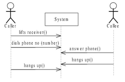
Figure 3.14: A System Sequence Diagram for the Make Phone Calls of a Telephone System
10. Recording system operations
The set of all required system operations are determined by identifying the system input events. The name of the input event and the name of the operation are identical; the distinction is that the input event is the named stimulus, the operation is the response.
For example, from the inspection of the use case Buy Items with Cash, we can identify the system operations to be:
- enterItem(upc, quantity)
- endSale()
- makePayment()
The system operations can be grouped as operations of a type named System. The parameter may optionally be ignored. Figure 3.15 shows a system concept showing identified system operation.
| System |
|---|
| enterItem() endSales() makepayment() |
Figure 3.15: System Concept Showing System Operations for a "But Items with Cash" Use Case
The system operations for "Make Phone Calls" use case is shown in Figure 3.16.
| System |
|---|
| liftsReceiver() dialPhoneNumber() answerPhone() hangUP() |
Figure 3.16: System Concept Showing System Operations for a "Make Phone Calls" Use Case
11. System Operations Contracts
Use cases describe system
behavior which is usually sufficient. But, sometimes a more detailed
description of system behavior is needed. Again system sequence diagram does
not describe the effect of the execution of an operation invoked. It is missing
the details necessary to understand the system response – the system behaviour.
Part of the understanding of the system behaviour is to understand the system
state changes carried out by system operations. A system state is a snapshot of
the system at a particular moment of time which describes the objects of
classes currently existing, current values of attributes of these objects, and
current links between the objects at that time. The execution of a system
operation changes the system state into another state:
- Old objects may be removed,
- New objects and links may be created, and
- Values for attributes of objects may be modified.
To describe detailed system behavior in terms of state changes to objects in the Domain Model, after a system operation has executed, contracts are being used. We need to know how to write a contract for a system operation. As explained by Liu, the contract of an operation is defined mainly in terms of its pre-conditions and post-conditions.
- Pre-conditions are the conditions that the state of the system is assumed to satisfy or must hold true before the execution of the operation
- Post-conditions are the conditions that the system state has to satisfy when the execution operation has finished, or the constraint that must hold true after the completion of an operation.
12. Documenting Contracts
Suggested schema by Liu, for presenting a contract is as shown in Table 3.11:
Table 3.11: Schema for Documenting a Contract of a System Operation
| Name | Name of a system operation and parameters |
| Responsibilities | A short description of the responsibility the operation |
| Type | Name of type (concept, software class, interface) |
| Cross References S | System function reference numbers, use cases, etc |
| Note | Design notes, algorithms, and so on |
| Exceptions | Exceptional cases |
| Output | Non-User Interface (UI) outputs, such as messages or records that are sent outside of the system |
| Pre-conditions | The conditions that the state of the system is assumed to satisfy before the execution of the operation |
| Post-conditions | Describes changes in the state of objects in the domain area. The sate changes can include: instances creation, associations formed or deletion and attributes changed. |
13. Contracts for Some Operations in POST system
Tables 3.12 and 3.13 show examples contracts for “enterItem” operation and “makePayment” operation of the POST system.
Table 3.12: Contract for enterItem Operation Contract
| Name | enterItem(upc:UPC, quantity:Integer): |
| Responsibilities: | Enter (or record) sale of an item and add it to the sale. Display the item description and price. |
| Type: | System |
| Cross References: | System Functions: R1.1, R1.3, R1.9 Use Cases, Buy Items: |
| Note: | Use superfast database access. |
| Exceptions: | If the UPC is not valid, indicate that it was an error. |
| Output: | |
| Pre-conditions: | UPC is known to the system. |
Table 3.13: Contract for makePayment Operation
| Name | makePayment(amount: Quantity). |
| Responsibilities: | Record the payment, calculate balance and print receipt |
| Type: | System |
| Cross References: | System Functions: R2.1 Use Cases: Buy Items |
| Note: | Use superfast database access
|
| Output: | |
| Pre-conditions: | |
| Post-conditions: | 1. A Payment was created (instance creation). 2. Payment.amountTendered was set to amount (attribute medication). 3. The Payment was associated with the Sale (association formed) 4. The Sale was associated with the Store, to add it to the historical log of completed sales (association formed). |
14. How to Create a Contract
Apply the following advice from Liu, to create a contract for a system operation
1. Identify the system operations from the system sequence diagram.
2. For each system operation, construct a contract.
3. Start by writing the Responsibilities section, informally describing the purpose of the operation.
4. Then complete the Post-conditions section, declaratively describing the state changes that occur to objects in the conceptual model.
5. To describe the post-conditions, use the following categories:
- Instances creation and deletion.
- Attributes modification.
- Associations formed and broken.
15. Conclusion
Relating the three models used so far in this unit, it can be observed that:
i. Use cases suggest the system input events and system sequence diagram.
ii. The system operations are then identified from system sequence diagrams.
iii. The effect of the system operation is described in contract within the context of the conceptual model.