 Print book
Testing Strategies
| Site: | Saylor Academy |
| Course: | CS302: Software Engineering |
| Book: | Testing Strategies |
| Printed by: | Guest user |
| Date: | Friday, February 4, 2022, 6:15 PM |
Description
In this section, you will learn about two kinds of testing strategies: how the logic is tested (via black-box and white-box testing) and how the testing is conducted (by top-down and
bottom-up testing).
Introduction
There are two kinds of testing strategies. The first type of strategy relates to how logic is tested in the application. Logic testing strategies are either black-box or white-box. Black-box testing strategies assume that module (or program or system) testing is concerned only that what goes in comes out correctly. The details of logic are hidden and not specifically analyzed. Black-box strategies are data-driven, which means that all test cases are based on analysis of data requirements for the test item.
White-box approaches to testing assume that specific logic is important and to be tested. White-box tests evaluate some or all of the logic of a test item to verify correct functioning. White-box strategies are logic-driven,
which means that all test cases are based on analysis of expected functions of the test item.
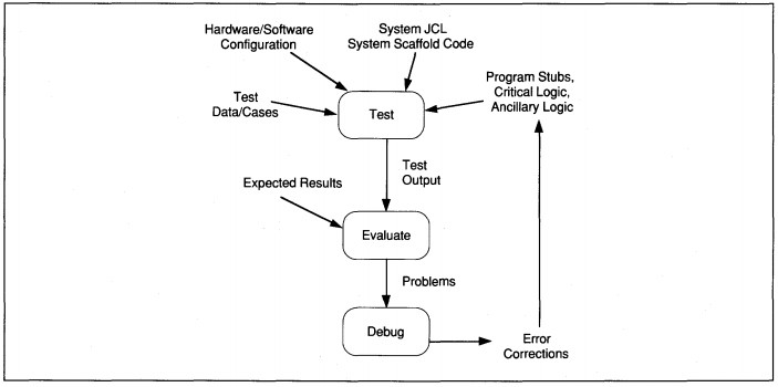
FIGURE 17-6 Testing Information Flow
The second type of testing strategy relates to how testing is conducted, regardless of logic testing strategy. These conduct, or process, strategies are top-down and bottom-up. Both top-down and bottom-up testing fit the project life-cycle phases in Figure 17 -1; the difference is in the general approach.
Top-down is incremental; bottom-up is 'all or nothing'. Top-down testing assumes the main application logic is most important. Therefore, the main logic should be developed and tested first and continuously throughout development. Continuous successful testing raises confidence levels about code reliability. Program stubs that contain minimal functional logic are tested first with additional logic added as it is unit tested. Top-down testing frequently requires extra code, known as scaffolding,
to support the stubs, partial modules, and other pieces of the application.
Bottom-up testing assumes that individual programs and modules are fully developed as standalone processes. These are tested individually, then combined for integration testing. Bottom-up testing treats test phases as somewhat discrete. Unit testing leads to integration testing which leads to system testing. The next section discusses variations of black-and white-box testing strategies.
Source: Sue Conger, https://learn.saylor.org/pluginfile.php/236045/mod_resource/content/2/The%20New%20Software%20Engineering.pdf
 This work is licensed under a Creative Commons Attribution 3.0 License.
Black-Box Testing
Black-box testing attends to process results as evidenced by data. The test item is treated as a black box whose logic is unknown. The approach is effective for single function modules and for high-level system testing. Three commonly used methods of black box testing are:
- equivalence partitioning
- boundary value analysis
- error guessing
A fourth method that is less common in business, cause-effect graphing, is also used. Each of these methods are described in this section.
Equivalence Partitioning
The goals for equivalence partitioning are to minimize the number of test cases over other methods and design test cases to be representative of sets of data. For the given level of test, the test item data inputs are divided into equivalent partitions
each representing some set of data. Then, test cases are designed using data from each representative, equivalent set. The theory is that by exhaustively testing one item from each set, we can assume that all other equivalent items are also exhaustively
tested.
For instance, at the module level, field values identify equivalent sets. If the field domain is a range of values, then one set is allowable values and the other set is disallowed values. The analysis to define equivalent domain sets continues for each data item in the input.
Equivalence partitioning gains power when used at more abstract levels than fields, however. For instance, interactive programs, for integration tests, can be defined as equivalent sets at the screen, menu selection, or process levels. At the system test
level, equivalence can be defined at the transaction, process, or activity level (from Information Engineering).
Test scripts for on-line applications can be black-box equivalence partitioning tools. A test script is an entry-by-entry description of interactive processing. A script identifies what the user enters, what the system displays in response, and what the
user response to the system should be. How any of these entries, actions, and displays takes place is not tested.
Boundary Value Analysis
Boundary value analysis is a stricter form of equivalence partitioning that uses boundary values rather than any value in an equivalent set. A boundary value is at the margin. For example, the domain for a month of the year ranges from one to 12. The
boundary values are one and 12 for valid values, and zero and 13 for the invalid values. All four boundary values should be used in test cases. Boundary value analysis is most often used at the module level to define specific data items for testing.
Error Guessing
Contrary to its name, error guessing is not a random guessing activity. Based on intuition and experience, it is easy for experts to test for many error conditions by guessing which are most likely to occur. For instance, dividing by zero, unless
handled properly, causes abnormal ending of modules. If a module contains division, use a test that includes a zero divisor. Since it is based on intuition, error guessing is usually not effective in finding all errors, only the most common ones.
If error guessing is used, it should always be used with some other strategy.
Cause-Effect Graphing
One shortcoming of equivalence and boundary testing is that compound field interactions are not identified. Cause-effect analysis compensates for this shortcoming. A cause-effect graph depicts specific transformations and outputs as effects and identifies the input data causing those effects. The graphical notation identifies iteration, selection, Boolean, and equality conditions (see Figure 17-7). A diagram of the effects works backward to determine and graph all causes. Each circle on the diagram represents a sequence of instructions with no decision or control points. Each line on the diagram represents an equivalent class of data and the condition of its usage. When the graph is done, at least one valid and one invalid value for each equivalent
set of data on the graph is translated into test case data. This is considered a black-box approach because it is concerned not with logic, but with testing data value differences and their effect on processing. An example cause-effect graph for Customer
Create processing is shown in Figure 17-8.
Cause-effect graphing is a systematic way to create efficient tests. The trade-off is in time to develop the set of graphs for an application versus the time consumed executing large numbers of less efficient, possibly less inclusive test cases. The technique is used more in aerospace than in general business.
Cause-effect graphs are more readily created from DFDs, PDFDs, and state-transition diagrams than from Booch diagrams even though it is particularly useful for real-time and embedded systems. Both types of systems use state-transition diagrams to show
the causes and effects of processing. A cause-effect graph can be superimposed on a state-transition diagram or easily developed from the state-transition diagram. Cause-effect graphing can be used in place of white-box approaches whenever specific
logic cannot be realistically tested because of combinatorial effects of multiple logic conditions.

FIGURE 17-7 Cause-Effect Graphical Notation
White-Box Testing
White-box testing evaluates specific execute item logic to guarantee its proper functioning. Three types of white-box techniques are discussed here: logic tests, mathematical proofs, and cleanroom testing. Logic coverage can be at the level of statements, decisions, conditions, or multiple conditions. In addition, for mathematically specified programs, such as predicate logic used in artificial intelligence applications, theorem proof tests can be conducted. The newest development in white-box strategies is the 'clean room' approach developed by IBM.
Logic Tests
Logic tests can be detailed to the statement level. While execution of every statement is a laudable goal, it may not test all conditions through a program. For instance, an if statement tested once tests either success or failure of the if. At least
two tests are required to test both conditions. Trying to test all conditions of all statements is simply not practical. In a small module with 10 iterations through a four-path loop, about 5.5 million test cases would be needed to try all possible
combinations of paths (i.e., 410 + 49 + 48 .•• + 41 ). Obviously, some other method of deciding test cases is needed. The other white-box logic testing strategies offer some alternatives.
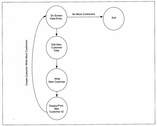
FIGURE 17-8 Cause-Effect Graph for Customer Create
Decision logic tests look at each decision in a module and generate test data to create all possible outcomes. The problem is that decisions are not always discrete and providing for compound decisions requires a different strategy. A problem with logic tests at this level is that they do not test module conformance to specifications. If the test is developed based on the specification, but the specification is interpreted differently by the programmer (for better or worse), the test is sure to fail. The solution to this issue is to require program specifications to detail all logic. While this may be practical for first- and second-generation languages (i.e., machine and assembler languages), it defeats the purpose of higher level, declarative languages.
Condition logic tests are designed such that each condition that can result from a decision is exercised at least once. In addition, multiple entry conditions are tested. Thus, condition tests are more inclusive than decision logic tests. They still suffer
from the problem of ignoring compound decision logic.
Multicondition tests generate each outcome of multiple decision criteria and multiple entry points to a module. These tests require analysis to define multicriteria decision boundaries. If the boundaries are incorrectly defined, the test is ineffective.
When designed properly, multicondition logic tests can minimize the number of test cases while examining a large number of conditions in the case. The use of this technique requires practice and skill but can be mentally stimulating and even fun.
Mathematical Proof Tests
When evaluating logic, the goal is zero defects. One method of approaching zero defects is to apply mathematical reasoning to the logic requirements, proving the correctness of the program. This method requires specifications to be stated in a formal
language such as the Vienna Development Method (VDM). Formal languages require both mathematical and logic skills that are beyond the average business SE's ability at the present time. An example of a general process overview for a payroll system
as specified in VDM is shown as Figure 17-9. While a detailed discussion of these methods is beyond the scope of this text, they deserve mention because they are the only known way for attaining zero defects and knowing it.
Cleanroom Tests
Cleanroom testing is an extension of mathematical proof that deserves some comment. Cleanroom testing is a manual verification technique used as a part of cleanroom development. The theory of cleanroom development is that by preventing errors from ever
entering the process, costs are reduced, software reliability is increased, and the zero defect goal is attained. The process was introduced in IBM in the early 1980s by Mills, Dyer, and Linger, and applies hardware engineering techniques to software.
Formal specifications are incrementally developed and manually verified by walk-through and inspections teams. Any program that is not easily read is rewritten. All program development is on paper until all verification is complete.
Cleanroom testing techniques are walk-throughs and formal mathematical verification. The goal is to decompose every module into functions and their linkages. Functional verification uses mathematical techniques, and linkage verification uses set theory whenever possible to prove the application design and code.
After verification, an independent testing team compiles and executes the code. Test data is compiled by analysis of the functional specification and is designed to represent statistical proportions of data expected to be processed by the live system.
In addition to normal data, every type of catastrophic error is produced to test that the application does degrade gracefully.
The success of cleanroom development and testing is such that more than 80% of reported projects have an average failure time of less than once every 500 software years. Software years are counted by number of sites times number of years of operation. For example, 100 sites for one year is 100 software years. This is an impressive statistic that, coupled with the 80-20 rule, can guide redevelopment of error-prone modules. The 80-20 rule says that 80% of errors are in 20% of modules. If those modules can be identified, they should be redesigned and rewritten. Modules for redevelopment are more easily identified using cleanroom techniques than other techniques. The disadvantages of cleanroom development are similar to those of mathematical proof. Skills required are beyond those of the average business SE, including math, statistics, logic, and formal specification language. We will say more about the 80-20 rule later.
Top-Down Testing
Top-down testing is driven by the principle that the main logic of an application needs more testing and verification than supporting logic. Top-down approaches allow comparison of the application to functional requirements earlier than a bottom-up approach. This means that serious design flaws should surface earlier in the implementation process than with bottom-up testing.
The major drawback to top-down testing is the need for extra code, known as scaffolding, to support the stubs, partial modules, and other pieces of the application for testing. The scaffolding usually begins with job control language and the main logic
of the application. The main logic is scaffolded and tested hierarchically. First, only the critical procedures and control logic are tested.
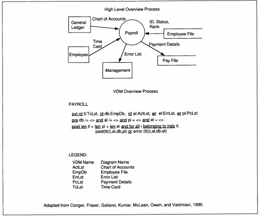
FIGURE 17-9 Vienna Development Method (VDM) Formal Specification Language Example
For example, Figure 17-10 shows the mainline logic for Customer Maintenance. The mainline of logic is important because it will be executed every time a maintenance request is performed. Since customer creation is the most probable maintenance activity, it should be guaranteed as much as possible. Further, if creation works, it is easily modified to provide update and delete capabilities which are a subset of creation functionality. Figure 17-11 is an example of COBOL stub logic for Create Customer. These two modules would be tested first, before any other logic is verified.
When critical procedures are working, the control language and main line code for less critical procedures are added. In the example above, the stubs for updating, deleting, and querying customers would be tested second. These are tested and retested throughout development as proof that the mainline of logic for all modules works.
After stubs, the most critical logic is coded, unit
tested, and placed into integration testing upon completion. In our example, the code for Create Customer would be tested next. The 'critical' code
includes screen data entry and writing to the file.
Finally, ancillary logic, such as editing input fields,
is completed and placed into testing. In our example,
the less critical code is the actual edit and validation
processing with error messages. Thus, in top-down
testing, the entire application is developed in a skeletal form and tested. As pieces of the skeleton are
fleshed out, they are added to the test application.
Procedure Division. Main-Line. Display Cust-Maint-menu. Accept Cust-Maint-Selection. If Cust-Maint-Selection =("A" or F6) Call Create-Customer else If Cust-Maint-Selection =("U" or F7) Call Update-Customer else If Cust-Maint-Selection =("D" or F8) Call Delete-Customer else If Cust-Maint-Selection =("R" or F9) Call Query-Customer else If Cust-Maint-Selection =("E" or F3) Go to Cust-Maint-Exit else Display Selection-Err Go To Main-Line. Cust-Maint-Exit. Exit. |
FIGURE 17-10 Mainline Logic for Customer
Maintenance
In theory, top-down testing should find critical
design errors earlier in the testing process than other
approaches. Also, in theory, top-down testing should
result in significantly improved quality of delivered
software because of the iterative nature of the tests.
Unit and integration testing are continuous. There is
no discrete integration testing, per se. When the unit/
integrated test is complete, further system tests are
conducted for volume and constraint tests.
Identification Division. Program-ID. CreateCust. Environment Division. Configuration Section. Source-Computer. IBM. Object-Computer. IBM. File Section. FD Customer-Screen ... 01 Customer-Screen-Record. ... screen description FD Customer-File ... 01 Customer-File-Record. ...customer record description Data Division. Working-Storage Section. 01 Cust-Screen. ... 01 Customer-relation. ... Procedure Division. Main-Line. Perform Display-Cust-Screen. Perform Accept-Values. Perform Edit-Validate. Perform Write-Customer. Display Continue-Msg. Accept Cust-Response. If Cust-Resp = 'yO go to main-line else go to create-customer-exit. Display-Cust-Screen. Write Cust-Screen from Customer-Screen-Record. DCS-exit. Exit. Accept-Values. AV-Exit. Exit. Edit-Validate. EV-Exit. Exit. Write-Customer. Write Customer-Relation from Customer-File-Record on error perform Cust-Backout-Err. WC-Exit. Exit. Create-Customers-Exit. Exit. |
FIGURE 17-11 COBOL Stub Program for
Customer Create
Top-down easily supports testing of screen designs and human interface. In interactive applications, the first logic tested is usually screen navigation. This serves two purposes. First, the logic for interactive processing is exhaustively exercised by the time all code and testing is complete. Second, users can see, at an early stage, how the final application will look and feel. The users can test the navigation through screens and verify that it matches their work.
Top-down testing can also be used easily with
prototyping and iterative development. Prototyping
is iterative and follows the same logic for adding
code as top-down testing. Presenting prototyping,
iterative development, and top-down testing together
for user concurrence helps ensure that prototypes
actually get completed.
Bottom-Up Testing
Bottom-up testing takes an opposite approach based on the principle that any change to a module can affect its functioning. In bottom-up testing, the entire module should be the unit of test evaluation. All modules are coded and tested individually. A fourth level of testing is frequently added after unit testing to test the functioning of execute units. Then, execute units are turned over to the testing team for integration and systems testing.
The next section discusses the development of test cases to match whatever strategy is defined. Then, each level of testing is discussed in detail with ABC Video test examples to show how to design each test.
Test Cases
Test cases are input data created to demonstrate that both components and the total system satisfy all design requirements. Created data rather than 'live,' production data, is used for the following reasons:1. Specially developed test data can incorporate all operational situations. This implies that each processing path may be tested at the appropriate level of testing (e.g., unit, integration, etc.).
2. Predetermined test case output should be predicted from created input. Predicting results is easier with created data because it is more orderly and usually has fewer cases.
3. Test case input and output are expanded to
form a model database. The database should statistically reflect the users' data in the
amount and types of records processed while
incorporating as many operational processing
paths as possible. The database is then the
basis for a regression test database in addition to its use for system testing. Production
data is real, so finding statistically representative cases is more difficult than creating
them.
Each test case should be developed to verify that specific design requirements, functional design, or code are satisfied. Test cases contain, in addition to test case input data, a forecast of test case output. Real or 'live' data should be used to reality test the modules after the tests using created data are successful.
Each component of an application (e.g., module,
subroutine, program, utility, etc.) must be tested with
at least two test cases: one that works and one that
fails. All modules should be deliberately failed at
least once to verify their 'graceful degradation'. For
instance, if a database update fails, the application
should give the user a message, roll back the processing to leave the database as it was before the
transaction, and continue processing. If the application were to abend, or worse, continue processing
with a corrupt database, the test would have caught
an error.
Test cases can be used to test multiple design requirements. For example, a requirement might be that all screens are directly accessible from all other screens; a second requirement might be that each screen contain a standard format; a third requirement might be that all menus be pull-down selections from a menu bar. These three requirements can all be easily verified by a test case for navigation that also attends to format and menu selection method.
The development of test case input may be facilitated by the use of test data generators such as
IEBDG (an IBM utility) or the test data generators
within some case tools. The analysis and verification
of processing may be facilitated by the use of
language-specific or environment-specific testing
supports (see Figure 17-12). These supports are
discussed more completely in the section on automated supports.
COBOL Language Supports: Display Exhibit Ready Trace Interactive Trace Snap Dump Focus Language Supports: Variable Display Transaction Counts Online Error Messages Online Help |
FIGURE 17-12 Examples of Language
Testing Supports
To insure that test cases are as comprehensive as
possible, a methodical approach to the identification
of logic paths or system components is indicated.
Matrices, which relate system operation to the functional requirements of the system, are used for this
purpose. For example, the matrix approach may be
used in
- unit testing to identify the logic paths, logic conditions, data partitions or data boundaries to be tested based on the program specification.
- integration testing to identify the relationships and data requirements among interacting modules.
- system testing to identify the system and user requirements from functional requirements and acceptance criteria.
An example of the matrix approach for an integration test is illustrated as Figure 17-13. The example shows a matrix of program requirements to be met by a suite of modules for Read Customer File processing. The test verifies that each module functions independently, that communications between the modules (i.e., the message format, timing, and content) are correct, and verifies that all input and output are processed correctly and within any constraints.
The functional requirements of the Read Customer File module are related to test cases in the matrix in Figure 17-13. The 11 requirements can be fully tested in at most seven test cases for the four functions.
|
Good Cust-ID |
Bad Cust-ID |
Missing ID |
Retrieve by Name (Good) |
Retrieve by Name (Bad) |
Good Credit |
Bad Credit |
Good Data |
Bad Data |
Call from GetValid Customer (Good) |
Call from GetValid Customer (Bad) |
|
|
|
|||||||||||
|
1. 2. |
x x |
x
|
x
|
x
|
x
|
x |
x |
|
|
x x |
x x |
|
|
|||||||||||
|
3. 4. |
x x |
x x |
x x |
x |
x |
x |
x |
x x |
x
|
x x |
x x |
|
Legend: 1. Read Customer 2. Check Credit 3. Create Customer 4. Display Customer |
|||||||||||
FIGURE 17-13 Read Customer File Requirements and Test Cases
Matching the Test Level to the Strategy
The goal of the testers is to find a balance between strategies that allows them to prove their application works while minimizing human and computer resource usage for the testing process. Noone testing strategy is sufficient to test an application.
To use only one testing strategy is dangerous. If only whitebox testing is used, testing will consume many human and computer resources and may not identify data sensitive conditions or major logic flaws that transcend individual modules (see Table
17-1). If only black-box testing is used, specific logic problems may remain uncovered even when all specifications are tested; type 2 errors are difficult to uncover. Top-down testing by itself takes somewhat longer than a combined top-down, bottom-up
approach. Bottom-up testing by itself does not find strategic errors until too late in the process to fix them without major delays.
In reality, we frequently combine all four strategies in testing an application. White-box testing is used most often for low-level tests-module, routine, subroutine, and program testing. Black-box testing is used most often for high-level tests-integration and system level testing. White-box tests find specific logic errors in code, while black-box tests find errors in the implementation of the functional business specifications. Similarly, top-down tests are conducted for the application with whole tested modules plugged into the control structure as they are ready, that is, after bottom-up development. Once modules are unit tested, they can be integration tested and, sometimes, even system tested with the same test cases.
Table 17-2 summarizes the uses of the box and live-data testing strategies for each level of test. Frequently black- and white-box techniques are combined at the unit level to uncover both data and logic errors. Black-box testing predominates as the level
of test is more inclusive. Testing with created data at all levels can be supplemented by testing with live data. Operational, live-data tests ensure that the application can work in the real environment. Next, we examine the ABC rental application
to design a strategy and each level of test.
TABLE 17-1 Test Strategy Objectives and Problems
|
|
|||
| Test Strategy | Method | Goal | Shortcomings |
|
|
|||
| White-Box | Logic | Prove processing. | Functional flaws, data sensitive conditions, and errors across modules are all difficult to test with white-box methods. |
| Black-Box | Data | Prove results. | Type 2 errors and logic problems difficult to find. |
| Top-Down | Incremental | Exercise critical code extensively to improve confidence in reliability. | Scaffolding takes time and may be discarded. Constant change may introduce new errors in every test. |
| Bottom-Up | All or nothing | Perfect parts. If parts work, whole should work. |
Functional flaws found late and cause delays. Errors across modules may be difficult to trace and find. |
|
|
|||
|
|
|||
| Level | General Strategy | Specific Strategy | Comments on USe |
|
|
|||
| Unit | Black-Box | Equivalence Partitioning | Equivalence is difficult to estimate. |
| Boundary Value Analysis | Should always be used in edit- validate modules. | ||
| Cause-Effect Graphing | A formal method of boundary analysis that includes tests of compound logic conditions. Can be superimposed on already available graphics, such as state-transition or PDFD. | ||
| Error Guessing | Not a great strategy, but can be useful in anticipating problems. | ||
| Math Proof, Cleanroom | Logic and/or mathematical proof | The best strategies for life- sustaining. embedded, reusable, or other critical modules, but beyond most business SE skills. | |
| White-Box | Statement Logic | Exhaustive tests of individual statements. Not desirable unless life-sustaining or threatening consequences are possible, or if for reusable module. Useful for ‘guessed’ error testing that is specific to the operational environment. | |
| Decision Logic Test | A good alternative to statement logic. May be too detailed for many programs. | ||
| Condition Logic | A good alternative providing all conditions can be documented. | ||
| Multiple Condition Logic | Desired alternative for program testing when human resources can be expended. | ||
| Live-Data | Reality Test | Can be useful for timing, performance, and other reality testing after other unit tests are successful. | |
| Integration | Black-Box | Equivalence Partitioning | Useful for partitioning by module. |
| Boundary Value Analysis | Useful for partitioning by module. | ||
| Cause-Effect Graphing | Useful for application interfaces and partitioning by module. | ||
| Error Guessing | Not the best strategy at this level. | ||
|
|
|||
TABLE 17-2 Test Level and Test Strategy
|
|
|||
| Level | General Strategy | Specific Strategy | Comments on Use |
|
|
|||
| Integration | Live-Data | Reality Test | Useful for interface and black-box tests after other integration tests are successful. |
| System/QA-Application Functional Requirements Test | Black-Box | Equivalence Partitioning | Most productive approach to system function testing. |
| Boundary Value Analysis | Too detailed to be required at this level. May be used to test correct file usage, checkpoint/rcstart, or other data-related error recovery. | ||
| Cause-Effect Graphing | Can be useful for intermodule testing and when combined with equivalence partitioning. | ||
| White-Box | Statement Logic | Not a useful test strategy | |
| Decision Logic Test | May be used for critical logic. | ||
| Condition Logic | May be used for critical logic. | ||
| Multiple Condition Logic | May be used for critical logic. | ||
| System/QA-Human Interface | Black-Box | Equivalence Partitioning | Useful at the level for screen and associated process and for screen navigation. |
| Boundary Value Analysis | Useful at screen level for associated process and screen navigation. | ||
| Useful for QA testing. | |||
|
|
|||
|
|
|||
| Level | General Strategy | Specific Strategy | Comments on Use |
|
|
|||
| System/QA-Human Interface | White-Box | Condition Logic | May be used for critical logic. |
| Multiple Condition Logic | May be used for critical logic. | ||
| System/QA-Constraints | Black-Box | Equivalence Partitioning | May be useful at the execute unit level. |
| Boundary Value Analysis | Should not be required at this level but could be used. | ||
| Cause-Effect Graphing | Might be useful for defining how to measure constraint compliance. | ||
| White-Box | Multiple Condition Logic | Could be used but generally is too detailed at this level of test. | |
| Live-Data | Reality Test | Useful for black-box type tests of constraints after created data tests are successful. | |
| System/QA-Peak Requirements | White-Box | Multiple Condition Logic | May be used for critical logic, but generally too detailed for this level of testing. |
| Live-Data | Reality Test | Most useful for peak testing. | |
|
|
|||