 Print book
Change Management
| Site: | Saylor Academy |
| Course: | CS302: Software Engineering |
| Book: | Change Management |
| Printed by: | Guest user |
| Date: | Friday, February 4, 2022, 6:16 PM |
Description
A critical component of project monitoring and control is change management. As business requirements and operating environments change all the time, the project manager has to manage change throughout the software development cycle from acquisition,
supply, development, operation, and then maintenance. The guiding principles, techniques, and tools for change management are discussed in this chapter.
Introduction
Nothing is rarer in information systems development than an application without changes. Users forget requirements and remember them late in the design. The business changes. Bugs get fixed and require documentation. Change occurs in all phases and all levels of application development. Procedures to manage change, therefore, are necessary to maintain sanity and order on the project team.
The three major types of change in an application's life cycle-requirements, software, and documentation-are discussed in this chapter. For each, the importance of the change management techniques is discussed. Then, for each, techniques for managing changes are developed. At the end of the chapter, automated tools are identified for collaborative work, documentation, reverse engineering, and code management. First, we discuss the importance of designing for maintenance, regardless of the environment, architecture, or item being developed.
Source: Sue Conger, https://learn.saylor.org/pluginfile.php/236045/mod_resource/content/2/The%20New%20Software%20Engineering.pdf
 This work is licensed under a Creative Commons Attribution 3.0 License.
Designing for Maintenance
Applications are usually in production for an average of eight years. Many applications are much older, having been patched and modified regularly for 10 or even 20 years. Applications that are flexible enough to withstand years of modification are designed with change in mind. That is, regardless of the methodology, independent modules with local effects are developed.
Programs with 10,000 lines of, for instance, COBOL procedure code, rarely are modified easily. Usually, they are such spaghetti, that if they ever work, it is due to good luck. Frequently, change is precarious and likely to cause problems in untouched parts of the program.
In this section, we discuss the techniques used in designing for maintenance. The first, reusable libraries, have been used widely in the aerospace industry. Because cost savings can now be demonstrated from reusable libraries, they are moving into other industry segments. Reusable modules are complete programs that perform some complete function. The next section relates methodology to maintenance effort and discusses how each methodology attempts to provide for maintenance. Finally, CASE tools are related to maintenance and change.
Reusability
Reusability is a property of a code module such that the module can be used, as is, by several applications. In designing for reuse, the goal is to identify modules for potential reuse. The two most popular methods of implementing code reuse are program templates and reusable modules.
Program templates consist of standard code that performs a simple function. For instance, there are three basic types of business programs: report, edit/ validate, and file update. For a report, there are standard sections for reading file data, formatting
the data, and writing the report (see Figure 18-1). Reading and writing can be standardized regardless of the data definition for input. The formatting of data must be customized. In writing the report, there are sections of code for beginning-of-page,
body-of-page, and end-of-page. There may be sections for beginning-of-report and end-of-report, too. The report program might or might not have an internal sort routine that changes the sequence of the input file.
Templates can be developed to describe the 12 or so most common variants of the three basic types of programs. For instance, a report program is developed with and without sorts. COBOL or some other procedural language is used to define the standard versions
and the only items left to the application programmer are procedures specific to the application.
The templates are stored as read only modules in a library. When a new use is defined, the module to be used is copied and given a new name. The newly named module is then modified and customized for its current use.
The advantage of a template is that a finite number of variations are developed and then are modified as needed for a specific use. There is little or no maintenance on the templates once they are developed, and only a few new templates per year would
ever be developed. The number of support staff could be close to zero.
A template is a partial program that is completed for a particular application. A reusable module is a small, single function, well-defined, and standardized program module that can be used as a called routine, or as a copy book in COBOL. For instance, a date edit routine might be developed as a reusable module (see Figure 18-2).
When a reusable module is desired, a library of reusable modules is studied to determine which ones fit the application's needs. For reusable modules that do fit an application, the individual module code is examined to verify that it performs as required. Then the module is called at the appropriate place in the application's processing.
Each application team determines which modules it might have that could be reused in its own or in other applications. Then the modules are singled out for special development as independent routines. The finished module is quality assurance tested by
the librarians to ensure that it performs as documented. The librarian is an expert in reusable standards, quality assurance testing, and code management techniques. Eventually, the code is stored in a reusable library whose contents are published
for application developers' use.
Publication of reusable library contents can be awkward. Paper might be too voluminous to be useful or cost-effective. Electronic publication requires indices to assist users in identifying potential modules for their use. The indices might include keywords to describe function, language, date of development, type of input, and so on. If indices are not coded to capture the essential characteristics of the modules, they are useless.
The amount of organizational support required to maintain reusable libraries has been the major impediment to reusable library adoption in most industries. Librarians test, store, and maintain references to the modules in the reusable library. A large number of modules, for instance over 1,000, makes maintenance of the library integrity and accuracy a major task. Locating modules for use is also a major task. Librarians become specialized in performing these functions. Without proper organizational support, reusable libraries soon become unused and useless.
The arguments for reuse are substantial. As much as 75% of all code on a typical business application is redundant, and therefore, a candidate for reuse. Database descriptions, program procedure templates, and individual modules are all candidates for
reuse that can save companies time and money in application development. The more reused code, the less extensive the custom code developed, the less extensive the testing required, and the less the cost of the application.
Identification Division. Program-1 D. ABCVIDADD. Environment Division. Configuration Section. Source-Computer. IBM-3080. Object-Computer. IBM-3080. File Section. Select Input-File from UR-D0001 as RPTIN. Select Report-File from UR-P001 as RPTOUT. File Division. Input Section. FD Input-File Block contains 100 records. Record contains 400 characters. 01 Input-File-Record Pic x(400). FD Report-File Block contains 1 record. Record contains 132 characters. 01 Report-File-Record Pic x(132). Working-Storage Division. 01 Miscellaneous-counters. 05 Page-Count Pic 99 value zero. 05 Line-Count Pic 99 value zero. 05 Input-record-count Pic 9(7) value zero. 05 Output-record-count Pic 9(7) value zero. 05 End-of-file-marker Pic 9 value zero. 88 End-of-file value 1. 88 Not-end-ot-file value 0. ******** 01 Copy Input-File-Description statement goes here. ******** 01 Report-Headers. 05 Header-01. 10 Filler pic x(45) Value spaces. 10 H1 pic x(23) value ‘Company Standard Header’. 10 Filler pic x(15) value spaces. 10 Date pic x(8) value spaces. 05 Header-2. 10 Filler pic x(45) Value spaces. 10 H1 pic x(23) value 'Report Standard Header'''. 10 Filler pic x(15) value spaces. 10 Time 15 Hour pic xx value spaces. 15 Filler pic x value 15 Hour pic xx value spaces. 15 Filler pic x value 15 Hour pic xx value spaces. |
FIGURE 19-1 Partial COBOL Program Template for a Report
Linkage Section. 01 In-Date. 05 In-Date-Month pic xx. 05 In-Date-Day pic XX. 05 In-Date-Year pic XX. 01 Errors. 05 Err-table occurs x times. 10 Err pic 9 comp. Procedure Division. Link. Enter linkage. Entry Link-date-edit using in-date, errors Enter COBOL. Initialize. Move zeros to Errs. Check-Numencs If In-Date-Mo not numeric move 1 to err(1). If In-Date-Day not numeric move 1 to err(2). If In-Date-Year not numeric move 1 to err(3). If err(1 ) - 1 or err(2) = 1 or err (3) = 1 go to End-Test Check-values If In-Date-Day > 0 continue else move 1 to err(4). If In-Date-Year > 1992 and In-Date-Year < 2015 continue |
FIGURE 18-2 Reusable COBOL Module for Date Edit
Methodology Design Effects
In this section, we discuss the suitability of reusable libraries and program templates to the three classes of methodologies. Because of the encapsulation of data and function in object orientation, object methods are best suited to the large scale development of reusable modules. The other methodologies, process and data, can use program templates and reusable modules, but such modules are not identified as naturally as with objects.
Object methods are best suited to reusable components because the design method results in small, single function modules automatically. The method assumes that only data needed for a function will be available to it when it is called. Thus, the entire method assumes and strives for modules that are potentially reusable. When a module is identified in object analysis as being invoked from multiple calling objects, it is automatically targeted as potentially reusable. Further analysis determines if the functionality is identical for all users. If the functionality is the same, the module becomes locally reusable.
The step from local reuse to organizational reuse is small, with the criteria being the number of other applications needing the function. Here too, object methods are more amenable to identifying reusable functionality at the analysis stage than the other methodologies. Think back to Chapter 11, in which we developed the table of actions (or functions) and the objects to which they were attached (see Table 18-1). It is at this stage that reuse is identified. When an action has more than one object attached, they are examined to determine whether the same action is performed for each. If both objects use the action identically, they are labeled potentially reusable.
else move 1 to err(5). If In-Date-Month = 2 If In-Date-Year = (1992 or 1996 or 2000 or 2004 or 2008 or 2012) If In-Date-Day < 30 go to End-Test else move 1 to err(6) else If In-Date-Day < 29 go to End-Test else move 1 to err(7) else If In-Date-Month = (4 or 6 or 9 or 11 ) If In-Date-Day < 31 go to End-Test |
FIGURE 18-2 Reusable COBOL Module for Date Edit (Continued)
Then, the potentially reusable actions are used to search the reusable library to see if similar actions in reusable form already exist. When a match is found, the reusable module code is examined to determine its fit to the current need. Based on the closeness of fit, the designers choose to design their own module or use the reusable module. The reusable module can be used as it exists or can be customized to exactly fit the application. The point is that the analysis action is matched to a reusable action at the logical level. Only when the logical actions match, the physical implementation is then examined for its appropriateness. When many such logical level matches are found, the time savings in analysis, design, and implementation can be considerable.
It has long been held that structured and modular design reduces maintenance effort by facilitating the definition of understandable chunks of analysis and designs. Modular design, in turn, is then applied to program modules. The designer uses his
or her experience, applying the principles of information hiding, minimal coupling and maximal cohesion, to develop single function modules. In this manner, the nonobject methodologies are more brute force methods of developing modules with object-like
properties. While the nonobject methodologies rely on personal designer knowledge, such knowledge also is more important in object methods than is commonly recognized at present. The results in nonobject methodologies, though, are less uniform and
less likely to cause ready recognition of reusable components than object methods. Therefore, reusable component libraries are most likely to be effective and widely used in object-oriented environments.
TABLE 18-1 Sample Actions with Related Objects
|
Verb from Paragraph |
Space |
Process Name |
Objects-Action* |
|
is entered |
S |
EnterCustPhone |
Customer, Data entry (DE) |
|
to create |
S |
CreateOrder |
Order (R) |
|
are displayed |
S |
DisplayOrderVOO |
Order VOO (D) |
|
are entered |
S |
EnterBarCode |
VOO (DE) |
|
are retrieved |
S |
RetrieveInventory |
VideoInventory (R) |
|
are displayed |
S |
DisplayInventory |
VideoInventory (R) |
|
Computes |
S |
ComputeOrderTotal |
Order (Process) |
|
is entered |
S |
EnterPayAMt |
Order (DE) |
|
is computed |
S |
ComputeChange |
Order (P) |
|
*Actions are (R)ead, (W)rite, Data Entry (DE), (D)isplay (P)rocess in memory, (PR)int |
|||
* Actions are (R)ead, (W)rite, Data Entry (DE), (D)isplay (P)rocess in memory, (PR)int
The opposite situation is true of program templates. The nonobject methods, because they are used mostly for COBOL applications, can take advantage of program template libraries easily and effectively. As much as 60-80% of all COBOL code is boilerplate, that is, code which does not vary from one program to another. The boilerplate can be standardized and provided as program templates.
With object methods, the boilerplate in an object package is minimal but still can be standardized. The remaining code is either reused or customized. The types of COBOL template programs, for instance, a report with a sort, do not exist in the same form as objects. There might be a report object and there might be a sort object, and both might be reusable, but the code for using either object is most likely provided by custom developed code.
Role of CASE
Computer Aided Software Engineering (CASE) tools are critical to maintaining applications at the functional level rather than at the code level. The argument for CASE runs something like this. The 40-20-40 rule applies to software engineering application development. The rule states that 40% of the work is performed during feasibility, analysis, and design; 20% is during coding; and the remaining 40% is during testing (see Figure 18-3).
The 80-20 rule also applies (see Figure 18-3). According to this rule, 20% of the development work is performed during the original application development. The other 80% is performed during maintenance. This ratio holds because maintenance is a much longer period of an application's life.
Putting these two rules together, to gain substantive productivity increases we need to reduce time spent on coding, testing, and maintenance more than we need to reduce the time spent on analysis and design. CASE that covers analysis and design only reduces the time spent on documentation and maintenance of documents. CASE that includes database schema generation and code generation further reduces the coding, testing, and maintenance activities. Fully integrated CASE tools, I-CASE (see Chapter
3 and Automated Tools section of this chapter), that interface with code generators, support all of these productivity improvements. With I-CASE tools, maintenance changes are reflected in the requirements for an application. The requirements are,
in turn, used to regenerate the database schemas and code for the application. Thus, the changes take place at the logical level and are automatically generated by the CASE tool at the physical level. The capability to do all application maintenance
in this way is not here yet but should be before the new century.
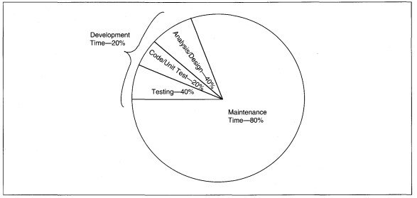
FIGURE 18-3 Application Life Cycle Time Distribution
A more futuristic feature of CASE tools will be the ability of the tool to recognize reusable analysis and design fragments, rather than relying on humans to recognize reusable code fragments. Purchasable options of the CASE tools will include intelligent
options to detect feature and function similarities across applications. The fragments would then be imported from the original library to the using application library (or repository). Very intelligent CASE will be able to recognize a design fragment,
logically link to the base definition of the reused item, and use already operational code modules. This level of intelligent CASE that could manage the use of reusable code may surface in our lifetimes, but not soon.
Application Change Management
IMPORTANCE
Applications frequently undergo redesign. Three typical conditions for redesign are assignment of a new management team, a project that is chronically over budget, late, and full of bugs, and the loss of the user-owner confidence that the SEs understand their needs. Even without drastic redesign, reviews (e.g., for user agreement or quality assurance) frequently turn up items that were originally compromised or rethought several times before final version agreement. The history of decisions and the reasoning about decisions is rarely kept as part of project notes. But, any project manager and SE can tell you that they frequently rehash the same arguments and reasonings over and over, even reaching the same conclusions.
In a paper-based work environment, keeping track of the history of decisions is not practical; so much paper would be generated that finding anything becomes impossible. In a CASE environment, or in an imaging environment, maintaining the history of application decisions electronically becomes a manageable, and sometimes desirable, activity. The ability to recall reasoning through a decision, whether it is logical or political, can save time and provide continuity between managers.
Finally, changes in the business, legal requirements, or stakeholders in the application can all necessitate legitimate changes to application designs. Knowing the history of decisions sometimes makes them more palatable and easier to convey to staff. For instance, being able to relate a change of design to a developing business situation helps those who must cope with the change appreciate the business of the application. If the change is to keep a valued customer or increase competitiveness in a new area, the systems developers are more likely to be enthusiastic about shifting design.
Changes can be to requirements, designs, programs, interfaces, hardware, or purchased software. Most changes are initiated from within the organization developing the application, but might be motivated by some outside event, such as a change in laws. Using change controls protects the development team from user whims while allowing for action on legitimate requests. The idea that a specification is frozen, meaning not changeable after it is accepted as complete, motivates users to be as complete in their thinking as possible.
Designs do not stay frozen forever. Usually, once an application begins coding, no changes are implemented until the application becomes operational. Then the project manager, SE, and user review the backlog of requests to develop priorities and plan the changes. Some changes may be so critical that the design is unfrozen to add the crucial functionality, regardless of the phase of development.
Change Management Procedures
Change control management is in effect from the time the work product is accepted as complete until the project is retired. First, baseline work products that are to be managed are identified. A baseline work product is a product that is considered complete and that is the basis for other, current work by the project development team. A baseline document would be, for instance, the functional requirements specification after it is accepted by the user.
A history of change request file actions for a functional specification are listed here as an example.
1. Create Open Request
2. File Impact Statement
3. File Approval of Schedule and Cost signed by User/Owner
4. Complete Project Manager's Check List for the Change
5. File Documentation relating to changes. If documentation or programs changed, identify date and items updates completed. If procedures or training changed, identify dates at which revisions were operationalized.
6. File Close Request Form Approved by User/Owner
7. Summarize Dates, Durations, and Costs
First, the baseline document is frozen, then change requests are added, but no action is taken. The fourth request, for example, might be urgent and receive immediate attention. When the functional specification is updated to accommodate the change, it is again frozen and the work continues. The three previous requests might have been added to the application if they did not significantly alter it. They may just as likely be ignored until after the application is implemented.
Changes can be classified in several ways. First, they can be classified by type as eliminating defects, improving performance, or changing functionality. Second, changes can be classified as required or optional. Third, change can be classified by priority
as emergency, mandatory with a required end date, mandatory with an open end date, or low priority. Usually, eliminating defects is a required emergency, while changing functionality is required mandatory maintenance, and improving performance is
optional and might have any priority.
Knowing the change request classification determines whether it is subject to change control or not. Emergency changes usually circumvent the change control procedures in that the activities might all be followed but they are documented after the change is complete. All other change types should be required to comply with change controls.
For example, changes to functional requirements can occur at any time, but once the functional requirements specification is approved, it is frozen until the application is operational. Changes are subject to change control: they are added to a change
request list for future consideration unless given an emergency designation.
|
||||||||||||||||||||||||||||||||||||||||||||||||||||||||||||||||||||||||||||||||||||||||||||||||||||||||||||||||||||||||
FIGURE 18-4 Sample Change Request Form
A procedure for change control (listed below) requires that a formal request for a change is submitted by the user to the project manager (PM).
1. User sends the project manager and owner (if different person) a Change Request form (see Figure 18-4).
2. Project manager and SE develop an impact statement. At this time, the project manager's Check List is used to identify all work actions and changes relating to the request.
3. The Change Request is discussed with the User/Owner to establish priority, schedule, and cost changes.
4. Agreement is formalized and User/Owner approval of schedule and cost changes is obtained.
5. Using the impact statement, application and all related documentation are changed. Implement the change. As tasks are complete, check off the task on the project manager's Check List.
6. User/Owner approval to close the request is obtained and the request is closed.
The PM and SE define the schedule and cost impacts of the change (see Figure 18-5). The changes are then discussed with the user. Based on the negotiation with the user, the change is assigned a priority for action, and the cost and schedule are changed.
The request, expected date of action, schedule change, and cost increments are added to a project history file. The changes may be monitored by a Change Control Clerk, a person charged with maintaining project history and change control records, and with issuing a monthly change control report. A Change Control File contains all requests, correspondence, and documentation about changes. An Open Change Request is created when the request is made and a change number is assigned. The open change request stays on file until the request is completed, closed, and reported.
As the change is made, affected items are updated, including the appropriate documentation, code, training, and so forth (see Figure 18-6). A project manager's check list is used to check off required actions. The new documentation is filed with the Change Control Clerk who distributes it to all interested parties.
The completion date for the change is entered in the Change Control File. The change is identified as closed in the next status report and the open request is removed from the Change Control File.
Depending on the organization, the IS executive might want to track change requests for projects to identify success in meeting requests. Overall costs of changes for a year are used as one indicator that an application is a candidate for either retirement or reengineering. In such cases, both costs and volumes of change requests are tracked through the change control process. Summary reports by project of the changes over a given period, or comparing periods (e.g., a current period compared to the same period last year) can be developed. Three such reports are shown as Figures 18-7 through 18-9 for total cost by type, cost and schedule impacts, and change requests, respectively.
Historical Decision Logging
At the beginning of the project, the project manager and SE decide to use tools to store the decision process. This means that either electronic group meetings are used or that a written version of meetings and decisions is maintained and stored in word processed form. With electronic meetings, the electronic transcripts are maintained. With manual recording, the old version is updated and renamed when a document changes. For instance, functional specifications for ABC might be named ABCFSmmddyy, where ABC is the company, FS abbreviates Functional Specification, and mmddyy is the date. The date portion of the name would change for every major change of the document. The change management procedure in the next section would be followed.
Documentation Change Management
- Documentation changes should be identified by a change table of contents at the beginning of each document. The change table of contents includes the effective date, affected sections of the document, and a summary of the change (see Figure 18-10). The purpose of the change table of contents is to summarize all changes for the reader.
Changes should be redlined in the text to identify the changed portion. If the old information is important, it may be moved to a footnote, dated, and labeled as a previous version. An example of this type of documentation change is shown in Figure 18-11. Keep in mind that you also keep the old version of the document for history.
|
|
|
||||||
|
Project # ___________________________ |
|
||||||
|
Project Name ______________________ |
|
||||||
|
CHANGE CONTROL IMPACT ASSESSMENT |
|||||||
|
|
|
Date _________________ |
|||||
|
|
|
Request # ___________ |
|||||
|
|
|
||||||
|
Impact of Change Request |
|
||||||
|
|
|
||||||
|
|
|
||||||
|
Impact |
|
||||||
|
Type |
Cost |
Person Days |
Business Days |
Budget Control |
|
||
|
A. |
_______ |
_______ |
_______ |
Initiation Date |
____________ |
||
|
B. |
_______ |
_______ |
_______ |
Request # |
____________ |
||
|
C. |
_______ |
_______ |
_______ |
Amount |
____________ |
||
|
D. |
_______ |
_______ |
_______ |
Approval Date |
____________ |
||
|
E. |
_______ |
_______ |
_______ |
|
|
||
|
F. |
_______ |
_______ |
_______ |
|
|
||
|
Total |
_______ |
_______ |
_______ |
|
|
||
|
|
|
||||||
|
|
|
||||||
|
STATUS |
Scheduled Completion |
Actual Completion |
|||||
|
Initiated Date |
__________ |
__________ |
|||||
|
Analysis Date |
__________ |
__________ |
|||||
|
Development Date |
__________ |
__________ |
|||||
|
Testing Date |
__________ |
__________ |
|||||
|
Implementation Date |
__________ |
__________ |
|||||
|
|
|
||||||
|
Comments: |
|
||||||
|
|
|
||||||
|
|
|
||||||
|
Initiator |
Date |
|
|
||||
|
Owner |
Date |
Project Manager |
Date |
||||
FIGURE 18-5 Sample Change Request Impact Form
|
|
|
|||
|
Project # ___________________________ |
Date _________________ |
|||
|
Project Name _______________________ |
Request # _____________ |
|||
|
PROJECT MANAGER CHANGE CONTROL CHECK LIST |
||||
|
|
||||
|
DEVELOPMENT |
||||
|
|
Required |
Completion Date |
||
|
1. QA/Documentation Review |
______________ |
___________________ |
||
|
2. Update Source Document(s) |
______________ |
___________________ |
||
|
3. Update Baseline Document(s) |
______________ |
___________________ |
||
|
4. Update Program Specifications |
______________ |
___________________ |
||
|
5. Revise Code |
______________ |
___________________ |
||
|
6. Update User Documentation |
______________ |
___________________ |
||
|
7. Update Operations Documentation |
______________ |
___________________ |
||
|
8. Other: _______________________ |
______________ |
___________________ |
||
|
_____________________________ |
|
|
||
|
|
|
|
||
|
IMPLEMENTATION |
||||
|
|
Required |
Completion Date |
||
|
1. Baseline Documents Update |
______________ |
___________________ |
||
|
2. Requirement Change |
______________ |
___________________ |
||
|
3. Design Changes |
______________ |
___________________ |
||
|
4. Programming Changes |
______________ |
___________________ |
||
|
Pgm #’s ____, ____, ____ |
______________ |
___________________ |
||
|
____, ____, ____ |
______________ |
___________________ |
||
|
5. Unit Testing |
______________ |
___________________ |
||
|
6. System/Regression Testing |
______________ |
___________________ |
||
|
7. Interface Changes |
______________ |
___________________ |
||
|
8. Operations Changes |
______________ |
___________________ |
||
|
9. Other: _______________________ |
______________ |
___________________ |
||
|
____________________________ |
|
|
||
|
|
|
|
||
|
Comments: |
||||
|
Initiator |
Date |
|
|
|
|
Owner |
Date |
Project Manager |
Date |
|
FIGURE 18-6 Project Manager's Change Check List
|
||||||||||||||||||||||||||||||||||||||||||||||||||||||||||||||||||||||||||||||||||||||||||||||||||||||||||||||||||||||||||||||||||||||||
FIGURE 18-7 Summary Report of Change Costs
|
||||||||||||||||||||||||||||||||||||||||||||||||||||||||
FIGURE 18-8 Summary Report of Cost and Schedule Impacts
|
||||||||||||||||||||||||||||||||||||||||||||||||||||||||||||||||||||||||||||||||||||||||||||||||||||||||||||||||||||||||||||||||||||||||||||||||||||||||
FIGURE 18-9 Summary of Change Requests
|
CHANGE PAGE
|
FIGURE 18-10 Sample Document Change Table of Contents
Software Management
Introduction
Two of the roles of the SE in software management are to recommend what type of maintenance should be performed and to select code maintenance software. These are discussed in this section.
Types of Maintenance
The types of maintenance are minor modifications, restructuring, reengineering, or rebuilding. Minor modifications are changes to existing code and can be any of the project manager classifications discussed above. Restructuring is the redevelopment of a portion of an application with a bridge to the old application. Reengineering is the reverse analysis of an old application to conform to a new methodology, usually Information Engineering or object orientation. Reengineering is also known as reverse engineering. Rebuilding is the retirement and redevelopment of an application.
To select the appropriate type of maintenance, several questions are asked (see Figure 18-12). First, ask if the software works. If the answer is no, you retire the old application. Then you reengineer and rebuild it using a methodology. If the answer
is yes, you continue to the next question: Does the application have a high maintenance cost? If the maintenance cost is low, the answer is no; then do a simple revision. If the answer is yes, immediately restructure the parts that do not work,
and reengineer the entire application as part of on-going work.
|
||||||
FIGURE 18-11 Sample Documentation Change with Old Contents
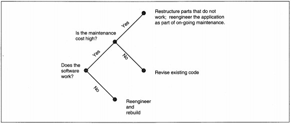
FIGURE 18-12 Decision Tree for Selecting the Maintenance Type
Reengineering
Reengineering is the analysis and design of an existing application to bring it into conformance with a methodology. When the application conforms to a methodology, it is rebuilt. To reengineer program code, the code first must be structured. Code restructuring can be done by automated tools. The restructured code from all programs in an application is entered into a CASE tool with reverse engineering capabilities.
Code restructuring also can be done manually. If no CASE products are used, the code is analyzed and the underlying data and process structures are mapped into a methodology. If Information Engineering is used, for instance, an entity relationship diagram (ERD) and a process data flow diagram (PDFD) are first developed for each program. Then, the diagrams are consolidated across programs to develop application ERDs and PDFDs. A data dictionary to document diagram contents is developed. The ERD is normalized and compared to the automated data to determine the extent of deviation from the normalized state. If the denormalized state was for performance purposes (this is an example of the importance of a historical file of design decisions), then problems with data integrity resulting from the denormalization should be noted for correction. Finally, the detailed process diagrams are used to develop a process hierarchy diagram. The hierarchy diagram is matched to the real organizational functions to determine the extent of application function redesign required.
If the methodology is object-oriented, the code modules are classified by object type and function. If multiple objects call a function, it is classified as reusable and set aside for further analysis. After module classification, the extent to which
the code matches a true object design is determined. Reusable modules are evaluated to ensure that they perform single functions, hide information, and use minimal coupling techniques. For minor deviation from the object method, individual modules or object types are reengineered to bring them into conformance with object tenets. For major deviation, the application is reengineered and redeveloped using object techniques.
Configuration Management
Introduction
In the mainframe world, one disk storage device can hold 10,000 or more different data files; large projects develop hundreds of program modules every year; and programmers may manage several different versions of code modules at one time. To support multiple users across different platforms might require multiple operational versions and variations of code modules, and they all have to be maintained. Configuration management is the identification, organization, and control of modifications to software built by a programming team. Code library management software provides a means to identify and manage the baseline for program code modules. The baseline is the official version of a code module that is in production use at any time. Two types of code libraries and the application types they support are discussed in this section. Derivations, which identify each module's history, are included in the discussion.
Configuration management addresses problems originally present in large COBOL applications but are equally useful for the more complex environments of object and distributed software. A programmer might keep several copies of a program and personally track which is in production at any one time. The problem with individual programmers maintaining their own copies is that eventually their multiple copies will diverge and knowing which is the most current can be a problem. Trusting individuals to be good librarians is asking for errors.
Assume next that one official version of programs exists. If several people are performing maintenance tasks on the one version of a program, a high probability exists that the changes of one person will interfere with the changes of the other person. Either the changes of one will be cancelled by being overwritten by the other, or one person will have to wait while the other makes the changes. Both situations lead to delays and are error prone.
In the complex world of distributed systems and multiple hardware/software platforms, different versions of the same software might be present. The only differences might be to accommodate platform idiosyncrasies, but such differences imply multiple versions of software that can cause maintenance problems. When a general change is made, somehow it must be verified as being made to all versions for all platforms. Specific changes for each platform must also be accommodated to allow fixing of bugs or changes that only affect one type of hardware.
Configuration management that consists primarily of code library management software plus manual procedures supports both single and multiple versions of programs to control for different platforms, evolving functionality, and debugging of software changes.
Types of Code Management
The most common code management procedure is the creation of derivations. The two code management types are for versions and variations. They can all be supported in the same software library or can be in separate libraries. Each type serves a different purpose.
Derivation
A derivation is a list that identifies the specific versions of multiple modules that were linked to create a load module or joint memory resident work unit. The purpose of a derivation is to allow tracing of errors that might be due to vendor software.
All software used to create a load unit are specifically identified with vendor, version, and last installation date. The sample shown in Figure 18-13 identifies specific platform, operating system, compiler, for creation of a work unit, and the dates
of the creation of each stage. If a problem were found, for example, a rounding error occurs in computing interest, the error is traced backward through the development software to find the problem. The program is checked first, then the compiler,
then the operating system, and so on. Let's say, for instance, that a new version of the compiler was installed one week before this module's creation, and that, upon inspection, the rounding algorithm used only allowed four decimal places to real
numbers. If more than four places are needed, a new compiler would be required.
The difference between a load module and joint memory resident work unit is in the dynamism of the processes. A load module is a compiled version of one or more source code modules that have been compiled and link-edited together, forming the load module. Compilation translates a module from source code to object (assembler) code. Linkage editing resolves references to other modules by replacing Call references with relative memory addresses, thus joining related modules for processing as a single work unit (see Figure 18-14).
A joint memory resident work unit is a series of load modules that work together in a dynamic, real-time environment. Linkage editing creates static modules that are fixed until the next linkage edit process. In real-time application environments, one goal of the procedures is to relieve the need to freeze specific module references until they are needed in operation. This liberates programmers from the linkage editing process but can create chaos when an error occurs and must be traced. Both situations require maintenance of derivations.
Recording of derivations requires precise identification of the software, option, code inputs, responsible person, and date that a load module was created (see Figure 18-15). The level of detail for derivations should match each process a module
undergoes from source code to load unit. This means that if the translation is from source code to load unit, there are two derivations. If the translations are from source to object to load unit, there are three derivations. All software used in
creating the derivation is recorded, including the compiler, linkage-editor, and so on, and their versions. Derivation maintenance provides an audit trail for software and is the only way that errors can be guaranteed to be traceable.
|
Work Unit Name: ________________ Creation Date: __________________
Comments:
|
FIGURE 18-13 Sample Derivation
Delta Version
Delta means difference. A delta file is a file of differences between versions of a program. Versions are multiple copies of a single program that represent incremental changes.
When a delta version is kept, the main program logic is maintained once. Then, the delta version is applied to the main logic, with specific lines of code being replaced to derive the delta (see Figure 18-16). The advantage of using a delta strategy is
that changes in functionality affect only the original code. The disadvantages are that loss or corruption of the original also affects all deltas, and that delta references based on code line numbers can lead to errors when the original changes.

FIGURE 18-14 Compile and Link Edit
Many software librarians and operating system editors work on the delta version principle. For instance, the Unix editor maintains delta versions of changes to text files, which includes program code. Using line numbers as the reference point, the original is stored. As changes are made, changed lines are kept plus new line numbers are appended in a delta file. When the file is referenced, the original is loaded into memory, then the deltas are applied until the memory version reflects all changes.
When using a delta version, then, it is important to create a new file periodically to save storage and processing time for delta overlays. This minimizes the extent to which you are making changes to changes. To create the new file, you save the old
file with a new name. Renaming modules is necessary to create a permanent version of the program with deltas incorporated into the saved version. Maintaining many renamed versions can cause errors in remembering the most current version, too.
Variation Storage
Variations are alternative, interchangeable program modules created for multiple environments or purposes. For instance, you might create an IBM PS/2 version of a program and a Novell Netware 386 version of a program. The functionality is the same, but specific modules are different to support the specific hardware/software platform.
Variations in a COBOL environment, for instance, might have a different interface for users in the United States and users in South America. Variations in an Ada environment, as another example, might be for performing the same process using integers
or using real numbers.
|
FIGURE 18-15 List of Requirements for Recording Derivations
Variations are named rather than numbered because there is no meaningful relationship between variations (see Figure 18-17). The name of each variation should reflect what makes it different. For instance, the names PS2S0RT (for PS/2 sort routine) and
N386S0RT (for Netware 386 sort routine), would be good variation names because they identify both the platform and the function of the variation.
Configuration Management Procedures
Strict configuration management requires that one person (or group) on each development and maintenance project be assigned as the project librarian. The project librarian is the only person authorized to write into the baseline library for the project. The procedure is summarized below.
1. File baseline code module.
2. Allow checkout for read-only purposes to individuals needing access. For instance, test team needs access for testing.
3. Allow chargeout for update to authorized programmers.
4. Monitor that chargeout items are returned.
5. Notify testers of chargein items for testing.
6. Verify that the text preamble to code identifies the change, date, programmer, and lines of code affected.
7. Chargein the item, refiling the module.
8. If derivations are used, file the derivation with project documentation.
When a project is in the code and unit test stage, the project librarian establishes an application library. As each module is unit tested and moves into subsystem and integration testing, the programmer's final version is given to the project librarian for addition to the library.
Error fixes, changes during testing, and maintenance changes are all managed the same way. The programmer tells the librarian she or he is checking the module out for update, and the librarian keeps track of this fact. The code is copied out of the library
and into the programmer's own workspace. The charges are made and unit tested. Upon completion of the unit test, the programmer gives the module and documentation to the librarian for reentry to the library.
The librarian checks that no other changes have been made during the time the programmer has the module out for update. If not, the module is rewritten into the library.
Depending on the library software used, additional features allow the librarian to issue a chargeout against a module. A charge-out causes a lock to be placed on the module such that no other chargeouts for update may be performed until the lock is removed. When the changed version of the code module is reentered into the library, a charge-in occurs. A charge-in is the updating of a charge-out module to remove the lock. The more intelligent the software, the more actions taken during charge-in. For instance, some library software packages initiate a regression test when a chargein action is, taken.
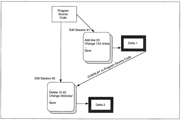
FIGURE 18-16 Delta Version Development
The disadvantage to having a formal project librarian is that the librarian becomes indispensable. The risk is that the librarian might become a bottleneck to updating the production library. For instance, if one person is the librarian, he or she might
be called for jury duty and be out of work for several weeks. During that time, unless another librarian is named, no updates can be performed.
Automated Tools for Change Management
There are different classes of automated tools for each type of change management. Each class of tools is discussed separately in this section.
Collaborative Work Tools
Collaborative work tools support group decision making and facilitate the development and historical maintenance of project decisions. Collaborative tools have developed out of research programs in group decision making at the Universities of Arizona and Minnesota in collaboration with IBM. Relatively primitive software of the 1980s for facilitating meetings has blossomed into a new industry for facilitating group work. Xerox Palo Alto Research Center (PARC) is a major contributor of new technology to this industry.
The specific technologies involved range from the relatively familiar, like electronic mail, or e-mail, to the exotic, for instance, media space clear boards that change our concepts of being there (see Table 18-2). Many of the technologies are emerging, but the emergence is at such a rapid rate that by the new century we will routinely use many of these technologies at work, if not at our homes.
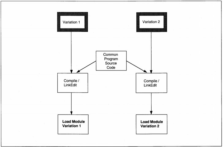
FIGURE 18-17 Variation Development
Media space technology allows several participants to sit on opposite sides of a clear glass board display that has electronics imbedded in it. The board can display computer images, text, and graphics as well as reflect hand-drawn notes and graphics of the meeting participants. The most effective use at the moment is between two people who both have clear access to the board. Clear boards allow people to see both the work and the co-worker, minimizing attention shift time. At the moment, the technology requires the people to be co-located, that is, in the same room; but the intention is to provide video conferencing capabilities using clear boards that are mirror images, thus simulating the face-to-face experience with the added electronic board interface. Thus, the user sees both the face of the other participant( s) and the contents of the board simultaneously. By removing the limitations of both time and geography our concept of being there is altered. By removing these limitations, clear board technology facilitates group work. This technology was developed, in this country, at Xerox PARC.
A different type of product provides a text-based communication environment that supports group passing of messages with storage of reader comments. Such a product, Notes provides an e-mail feature with the capability of user-built discussion forums and other data-sharing features. These products allow the development of decisions, history of the process, and easy sharing of information within and between work groups.
TABLE 18-2 Collaborative Work Tools
| Tool | Vendor | Functions |
|
Cruiser®™ |
Bellcore Morristown, NJ |
A video windowing system that allows the user to cruise offices visually and, perhaps, initiate a visit. Uses telephone and video technologies. |
|
Greyboard |
NeXT Computer Mountain View, CA |
Multiuser drawing program |
|
Groupkit |
Dept, of Computer Science University of Calgary Calgary, Alberta, Canada |
Real-Time Conferencing Toolkit; requires Interviews Software, Unix running X-Windows |
|
Notes |
Lotus Development Corp. MA |
E-mail, group bulletin board, data sharing |
|
Oracle Mail, Alert, Toolkit, and Glue |
Oracle Corp. Redwood City, CA |
E-mail, application development, and application programming interfaces for LANs |
|
Timbuktu™ |
Farallon Computing, Inc. Berkeley, CA |
Sharing of single-user software among several users |
|
Video Whiteboard |
ACM SIGCH1 Proceedings ’91, pp. 315-322 |
Wall-mounted whiteboard that portrays shadow of the other user |
|
VidcoDraw |
ACM SIGCHI Proceedings ’90, pp. 313-320 |
Multiuser drawing program |
|
Windows for Workgroups |
Microsoft, Inc. Belleview, WA |
LAN-based windows sharing |
Documentation Tools
Word processing tools, such as WordPerfect, are rapidly being replaced with more sophisticated and intelligent products for document development and maintenance (see Table 18-3).
In the old days of the 1980s, word processors became sophisticated enough to support such functions as redlining, the identification of changes in documents by means of a vertical line drawn in the margin of the change area. Typical word processors that merely automate the document preparation, such as redlining, still require significant text manipulation and creation of multiple documents with redundant information. Newer tools are beginning to emerge in the workplace that will eventually become as important as word processing has been.
One drawback of serial, word-processed text is that ideas that interrelate to many different topics either have to be replicated or cross-referenced in some way. Hypertext software eliminates that need by allowing any number of associative relationships
to be defined for a given text item. Hypermedia extend hypertext to support audio, video, image, graphics, text, and data. In hypermedia, these multiple technologies may all be interrelated and coresident in one environment. In addition, because these
tools do not restrict the number of connections an item may have, and because they use mainstream computer technology, application documentation remains on-line and interactively available to all users. Of course, interactive availability also implies
a need for hyperlibrary management to control changes to library contents.
TABLE 18-3 Documentation Maintenance Tools
|
Tool |
Vendor |
Functions |
|
Folio Views |
Folio Provo, UT |
Works with Word Perfect to provide multimedia support, highlighting and post-it type document annotation. |
|
Hypertext™ |
Apple Computer Cupertino, CA |
Associative management of text and graphics |
|
MS/Word |
Microsoft, Inc. Belleview, WA |
Word processing |
|
Word Perfect and Word Perfect Mac with Grammatik |
Word Perfect Corp. Orem, UT |
Word processing plus grammar checking |
|
Words and Beyond |
Lundeen and Associates Alameda, CA |
Documentation production including text and graphics |
Tools for Reverse Engineering of Software
Reverse engineering tools are rapidly becoming sophisticated enough that the needs for human intervention and extensive training to understand them are diminishing. Several CASE products support reverse engineering through the analysis of code to determine data and process structures that underlie the code (see Table 18-4). Individual programs are analyzed at this point. By the next century, whole applications will be able to be analyzed with intelligent functions pointing out inconsistencies and errors across the old 'spaghetti' code. All tools represented in this section are available in the market and are rated as usefully working products.
Tools for Configuration Management
Configuration management tools, commonly called software libraries or code libraries, have been around since the early 1970s (see Table 18-5). The more sophisticated, newer models make version and variation management simpler by supporting complex functions, such as conditional compilation.
Summary
To increase productivity in the application life cycle and reduce time spent in the code, test, and maintenance phases are important. To reduce the effort in these phases, applications should use change control, design for maintenance, use reusable libraries, and use code templates. Object methods are best suited to reusable libraries; nonobject methods are best suited to program templates.
I-CASE is critical in reducing coding and testing through automatic code generation. I-CASE is also required to build intelligence to support reusable designs.
If managing application change, change control procedures and management are critical. Requirements, designs, programs, interfaces, hardware, or purchased software are all subject to change. Change management procedures track requests from initiation through implementation and allow management reporting of cost, types, and impacts of changes.
Logging and management of historical decisions can be useful in volatile environments in which applications are subject to redevelopment. A historical decision log keeps track of arguments, reasoning, and rationales for decisions as they are made. After
an application enters operation, documentation is still subject to change to reflect the current state of the application. A document table of contents summarizes all changes and the parts of the document affected by each change. Similarly, software
documentation is kept in derivations to summarize the actual software and steps used to develop a load module or work unit. Configuration management is the use of software code libraries to manage the official, operational code modules of an application.
Delta version and variation management are the principle techniques.
TABLE 18-4 Reverse Engineering Tools
Via/Renaissance
|
Tool |
Vendor |
Functions |
|
ADW/Maintcnancc Workstation |
KnowledgeWare, Inc. Atlanta, GA |
Reverse engineering for information engineering: Entity-relationship diagrams Process data flow diagrams |
|
Bachman Series |
Bachman Information Systems, Inc. Burlington, MA |
Reverse engineering of data structures |
|
Design Recovery |
Intersolv, Inc. |
Reverse engineering of program structure |
|
Ensemble |
Cadre Technologies, Inc. Providence, RI |
Reverse engineering charts, metrics, and design |
|
Hindsight |
Advanced Software Automation, Inc. Santa Clara, CA |
Reverse engineering of C-language code: documentation, structure charts, complexity analysis |
|
RE for IE |
Texas Instruments, Inc. with Price Waterhouse Dallas, TX |
Reverse engineering for information engineering: Entity-relationship diagrams Process data flow diagrams |
|
Smartsystem |
Procase Corp. Santa Clara, CA |
Reverse engineering of C-language code: function call graphing, syntax and consistency checking |
|
Viasoft, Inc. Phoenix, AZ |
Reverse engineering of data structures |
TABLE 18-5 Software Configuration Management Tools
| Tool | Vendor | Functions |
|
Pandata |
IBM Armonk, NY |
Software code library for IBM and compatible mainframes |
|
Copylib |
Data Administration, Inc. |
Data management software—Allows viewing of file definitions from Librarian, Panvalet, and Copylibs, to locate occurrences and variations of data. |
|
Data Expeditor |
Pansophic Systems Lisle, IL |
Software code library for IBM and compatible mainframes |
| Librarian |
Pansophic Systems, Inc. Lisle, IL |
Software code library for IBM and compatible mainframes |