Slow sand filtration water treatment plants
Practical Action
OPERATION AND MAINTENANCE
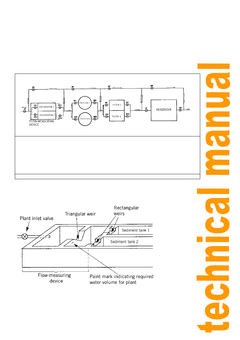
A flow-measuring device should be installed at the entrance to the treatment plant, as well as
a corresponding inlet valve to regulate the operating flow in the plant.
Below is a valve scheme for the conveyance of treated water. The bypass valves (B) enable
the plant to continue operating even when a unit is out of service.
P Plant entrance
IS 1 Entrance to sedimentator 1
IS 2 Entrance to sedimentator 2
SS 1 Sedimentator 2 outlet
SS2 Sedimentator 2 outlet
BS By pass sedimentators
IP 1 Entrance to pre-filter 1
SP1 Pre-filter 1 outlet
IP2 Entrance to pre-filter 2
SP2 Pre-filter 2 outlet
BP Pre-filter Bypass
IF1: Entrance to filter 1
F1 Filter 1 outlet
IF2 Entrance to filter 2
SF2 Filter 2 outlet
BF Filter by pass
IR Reserved income
SR Reservoir outlet
BR Reservoir by pass
VALVE SCHEME FOR TREATED WATER CONVEYANCE
For the flow-measuring device, a triangular weir and two rectangular weirs are recommended,
as shown in the figure.
In order to regulate the flow, the IP inlet valve is switched on until the water in the triangular
weir reaches the paint mark, which indicates the plant’s operating flow. The rectangular
weirs serve to make sure that the water enters the two sediment tanks evenly. Two simple
wooden sluice gates serve the purpose of the IS1 and IS2 valves, shutting off water flow into
a sediment tank during maintenance.
18